|
Os motores de busca de Datasheet de Componentes eletrônicos |
|
|
Os motores de busca de Datasheet de Componentes eletrônicos |
|
AD9761ARS Folha de dados(PDF) 6 Page - Analog Devices |
|
|
|||||||||||||||||||||||||||||
AD9761ARS Folha de dados(HTML) 6 Page - Analog Devices |
|
|
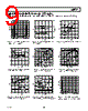
6 / 23 page  AD9761 –6– REV. A PIN FUNCTION DESCRIPTIONS Pin No. Name Description 1 DB9 Most Significant Data Bit (MSB). 2–9 DB8–DB1 Data Bits 1-8. 10 DB0 Least Significant Data Bit (LSB). 11 CLOCK Clock Input. Both DACs’ outputs updated on positive edge of clock and digital filters read respective input registers. 12 WRITE Write input. DAC input registers latched on positive edge of write. 13 SELECT Select Input. Select high routes input data to I DAC, select low routes data to Q DAC. 14 DVDD Digital Supply Voltage (+2.7 V to +5.5 V). 15 DCOM Digital Common. 16 COMP3 Internal Bias Node for Switch Driver Circuitry. Decouple to ACOM with 0.1 µF capacitor. 17 QOUTA Q DAC Current Output. Full-scale current when all data bits are 1s. 18 QOUTB Q DAC Complementary Current Output. Full-scale current when all data bits are 0s. 19 REFLO Reference Ground when Internal 1.2 V Reference Used. Connect to AVDD to disable internal reference. 20 REFIO Reference Input/Output. Serves as reference input when internal reference disabled. Serves as 1.2 V reference output when internal reference activated. Requires 0.1 µF capacitor to ACOM when inter- nal reference activated. 21 FSADJ Full-Scale Current Output Adjust. Resistance to ACOM sets full-scale output current. 22 COMP2 Bandwidth/Noise Reduction Node. Add 0.1 µF to AVDD for optimum performance. 23 AVDD Analog Supply Voltage (+2.7 V to +5.5 V). 24 ACOM Analog Common. 25 IOUTB I DAC Complementary Current Output. Full-scale current when all data bits are 0s. 26 IOUTA I DAC Current Output. Full-scale current when all data bits are 1s. 27 COMP1 Internal Bias Node for Switch Driver Circuitry. Decouple to AGND with 0.1 µF capacitor. 28 RESET/SLEEP Power-Down control input if asserted for four clock cycles or longer. Reset control input if asserted for less than four clock cycles. Active high. Connect to DCOM if not used. Refer to RESET/SLEEP section. PIN CONFIGURATION 14 13 12 11 17 16 15 20 19 18 10 9 8 1 2 3 4 7 6 5 TOP VIEW (Not to Scale) 28 27 26 25 24 23 22 21 AD9761 (MSB) DB9 IOUTB IOUTA COMP1 RESET/SLEEP DB8 DB7 DB6 COMP2 AVDD ACOM DB5 DB4 DB3 DB2 DB1 (LSB) DB0 REFLO REFIO FSADJ CLOCK WRITE SELECT DVDD QOUTB DCOM COMP3 QOUTA |
|
|
Ligação URL |
| ALLDATASHEET é útil para você? [ DONATE ] |
Sobre Alldatasheet | Publicidade | Contato conosco | Privacy Policy | Link para a ficha técnica | roca de Link | Lista de Fabricantes All Rights Reserved©Alldatasheet.com |
| Russian : Alldatasheetru.com | Korean : Alldatasheet.co.kr | Spanish : Alldatasheet.es | French : Alldatasheet.fr | Italian : Alldatasheetit.com Portuguese : Alldatasheetpt.com | Polish : Alldatasheet.pl | Vietnamese : Alldatasheet.vn Indian : Alldatasheet.in | Mexican : Alldatasheet.com.mx | British : Alldatasheet.co.uk | New Zealand : Alldatasheet.co.nz |
|
Family Site : ic2ic.com |
icmetro.com |
 Portuguese ▼
 English
 Chinese
 German
 Japanese
 Russian
 Korean
 Spanish
 French
 Italian
 Portuguese
 Polish
 Vietnamese
 Indian
 Mexican
 British
 New Zealand