|
Os motores de busca de Datasheet de Componentes eletrônicos |
|
|
Os motores de busca de Datasheet de Componentes eletrônicos |
|
LTC3602 Folha de dados(PDF) 10 Page - Linear Technology |
|
|
|||||||||||||||||||||||||||||
LTC3602 Folha de dados(HTML) 10 Page - Linear Technology |
|
|
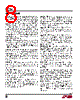
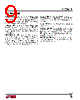
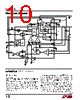
10 / 36 page  LTC3613 10 3613fa FUNCTIONAL DIAGRAM ICMP EA (gm(EA) = 1.7mS) 0.645V 0.555V 0.6V 1μA IREV LOGIC CONTROL PLL SYSTEM ONE-SHOT TIMER CLOCK DETECT OSCILLATOR LDO OUT EN IN SVIN 4.2V TIME ADJUST STOP START 1.2V 0.75V – + + – + DA (A = 1) RPGD PGOOD MODE/PLLIN VRNG ITH VOSNS – VOSNS + TRACK/SS SENSE– SENSE+ PGND SW EXTVCC BO0ST INPUT SUPPLY DB CB MT MB L COUT RFB2 RFB1 RSENSE PVIN INTVCC INTVCC SGND RITH CITH1 INTVCC R1 INTVCC R2 3.65V UVLO 4.6V VOUT RT RT RUN 1.3μA CVCC VIN CIN VOUT CIN CSS 3613 FD + – UV + – + – – + – – OV + – TG DRV BG DRV CLOCK OPERATION Main Control Loop The LTC3613 uses valley current mode control to regulate the output voltage in a monolithic, all N-channel MOSFET DC/DC step-down converter. Current control is achieved by sensing the inductor current across SENSE+ and SENSE–, either by using an explicit resistor connected in series with the inductor or by implicitly sensing the inductor’s resis- tive (DCR) voltage drop through an RC filter connected across the inductor. In normal steady-state operation, the top MOSFET is turned on for a fixed time interval proportional to the delay in the one-shot timer. The PLL system adjusts the delay in the one-shot timer until the top MOSFET turn-on is synchro- nized either to the internal oscillator or the external clock input if provided. As the top MOSFET turns off, the bottom MOSFET turns on with a small time delay (dead time) to avoid shoot-through current. The next switching cycle is initiated when the current comparator, ICMP, senses that inductor current has reached the valley threshold point (Refer to Functional Diagram) |
|
Ligação URL |
| ALLDATASHEET é útil para você? [ DONATE ] |
Sobre Alldatasheet | Publicidade | Contato conosco | Privacy Policy | Link para a ficha técnica | roca de Link | Lista de Fabricantes All Rights Reserved©Alldatasheet.com |
| Russian : Alldatasheetru.com | Korean : Alldatasheet.co.kr | Spanish : Alldatasheet.es | French : Alldatasheet.fr | Italian : Alldatasheetit.com Portuguese : Alldatasheetpt.com | Polish : Alldatasheet.pl | Vietnamese : Alldatasheet.vn Indian : Alldatasheet.in | Mexican : Alldatasheet.com.mx | British : Alldatasheet.co.uk | New Zealand : Alldatasheet.co.nz |
|
Family Site : ic2ic.com |
icmetro.com |
 Portuguese ▼
 English
 Chinese
 German
 Japanese
 Russian
 Korean
 Spanish
 French
 Italian
 Portuguese
 Polish
 Vietnamese
 Indian
 Mexican
 British
 New Zealand