|
Os motores de busca de Datasheet de Componentes eletrônicos |
|
|
Os motores de busca de Datasheet de Componentes eletrônicos |
|
SPT7936 Folha de dados(PDF) 6 Page - Cadeka Microcircuits LLC. |
|
|
|||||||||||||||||||||||||||||
SPT7936 Folha de dados(HTML) 6 Page - Cadeka Microcircuits LLC. |
|
|
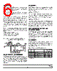
6 / 8 page  6 8/1/00 SPT7936 ANALOG INPUT The SPT7936 has a differential input that should have a common mode voltage of +1.5 V. The input voltage range is determined by the reference voltages which may be gener- ated internally or applied externally. The input of the SPT7936 can be configured in various ways depending on if a single-ended or differential, AC- or DC- coupled input is desired. The AC coupled input is most conveniently implemented using a transformer with a center tapped secondary winding. The center tap is connected to the VCM pin as shown in figure 2. To obtain low distortion, it is important that the selected transformer does not exhibit core saturation at the full-scale voltage. Excellent results are obtained with the Mini Circuits T1-6T or T1-1T. Proper termination of the input is important for input signal purity. A small capacitor across the inputs attenuates kickback noise from the internal sample and hold. Figure 3 illustrates a solution (based on operational amplifi- ers) that can be used if a a DC coupled single-ended input is desired. The selection criteria of the buffer op-amps is as follows: - Open loop gain >75 dB - Gain bandwidth product >50 MHz - Total harmonic distortion ≤-75 dB - Signal to Noise ratio >75 dB REFERENCES The SPT7936 can use either an internal or external voltage reference. When the digital input EXTREF is high, the exter- nal reference is used. When EXTREF is low, the internal reference is used. INTERNAL REFERENCE The internal references are set at +1.0 V and +2.0 V. When the internal reference is used, the full-scale range of the analog input is set at ±1.0 V differential. Do not connect external references when the internal reference is used. EXTERNAL REFERENCE When external references are used, the voltages applied to the VREF+ and VREF- pins determine the input voltage range which is equal to ±(VREF+ - VREF-). Externally generated reference voltages must be connected to these pins and should be symmetric about the common mode voltage. (See figure 2, Typical Interface Circuit.) COMMON MODE OUTPUT VOLTAGE REFERENCE CIRCUIT The SPT7936 has an on-board common mode voltage refer- ence circuit (VCM). It is set at +1.5 V and can drive loads of up to 20 µA. This circuit is commonly used to drive the center tap of the RF transformer in fully differential applications. For single-ended applications, this output can be used to provide the level shifting required for the single-to-differential con- verter conversion circuit. BIAS CIRCUITS The best AC performance is achieved when the bias currents are optimized for the selected sample rate. Two digital input pins are provided to control the optimum internal bias cur- rents. Table I shows the settings for Bias 0 and Bias 1 at selected frequencies. Table I - Frequencies for Biases 0 and 1 Typical Power Dissipation Bias 1 Bias 0 Description Ext. Ref. Int. Ref. 0 0 Sleep mode (power save)* 25 mW 36 mW 01 ≤5 MHz sampling 61 mW 73 mW 10 ≤20 MHz sampling 172 mW 184 mW 11 ≤28 MHz sampling 248 mW 260 mW *Clock = 28 MHz Figure 3 - DC-Coupled Single-Ended-to-Differential Conversion (Power Supplies are Not Shown) VCM R3 (R3)/2 + _ Input Voltage ( ±0.5 V) R3 R R2 R2 + _ + _ R RR 51 Ω 51 Ω R ADC VIN+ VIN– 15 pF 51 Ω POWER SUPPLIES AND GROUNDING The SPT7936 is operated from a single power supply in the range of 3.0 to 3.6 volts. Nominal operation is suggested to be 3.3 volts. All power supply pins should be bypassed as close to the package as possible. The analog and digital grounds should be connected together with a ferrite bead as shown in the typical interface circuit and as close to the ADC as possible. |
|
|
Ligação URL |
| ALLDATASHEET é útil para você? [ DONATE ] |
Sobre Alldatasheet | Publicidade | Contato conosco | Privacy Policy | Link para a ficha técnica | roca de Link | Lista de Fabricantes All Rights Reserved©Alldatasheet.com |
| Russian : Alldatasheetru.com | Korean : Alldatasheet.co.kr | Spanish : Alldatasheet.es | French : Alldatasheet.fr | Italian : Alldatasheetit.com Portuguese : Alldatasheetpt.com | Polish : Alldatasheet.pl | Vietnamese : Alldatasheet.vn Indian : Alldatasheet.in | Mexican : Alldatasheet.com.mx | British : Alldatasheet.co.uk | New Zealand : Alldatasheet.co.nz |
|
Family Site : ic2ic.com |
icmetro.com |
 Portuguese ▼
 English
 Chinese
 German
 Japanese
 Russian
 Korean
 Spanish
 French
 Italian
 Portuguese
 Polish
 Vietnamese
 Indian
 Mexican
 British
 New Zealand