|
Os motores de busca de Datasheet de Componentes eletrônicos |
|
|
Os motores de busca de Datasheet de Componentes eletrônicos |
|
TLC393D Folha de dados(PDF) 7 Page - Texas Instruments |
|
|
|||||||||||||||||||||||||||||
TLC393D Folha de dados(HTML) 7 Page - Texas Instruments |
|
|
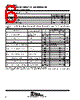
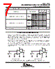
7 / 23 page  TLC193, TLC393 DUAL MICROPOWER LinCMOS ™ VOLTAGE COMPARATOR SLCS115D – DECEMBER 1986 – REVISED JANUARY 1999 7 POST OFFICE BOX 655303 • DALLAS, TEXAS 75265 switching characteristics, VDD = 5 V, TA = 25°C (see Figure 3) PARAMETER TEST CONDITIONS TLC393C, TLC393I TLC393Q, TLC193M, TLC393M UNIT MIN TYP MAX Overdrive = 2 mV 4.5 f10 kH Overdrive = 5 mV 2.5 tPLH Propagation delay time, low-to-high-level output f = 10 kHz, CL =15 pF Overdrive = 10 mV 1.7 µs CL = 15 F Overdrive = 20 mV 1.2 Overdrive = 40 mV 1.1 VI = 1.4-V step at IN + 1.1 Overdrive = 2 mV 3.6 f10 kH Overdrive = 5 mV 2.1 tPHL Propagation delay time, high-to-low-level output f = 10 kHz, CL =15 pF Overdrive = 10 mV 1.3 µs CL = 15 F Overdrive = 20 mV 0.85 Overdrive = 40 mV 0.55 VI = 1.4-V step at IN + 0.10 tf Fall time, output f = 10 kHz, CL = 15 pF Overdrive = 50 mV 22 ns PARAMETER MEASUREMENT INFORMATION The TLC393 contains a digital output stage which, if held in the linear region of the transfer curve, can cause damage to the device. Conventional operational amplifier/comparator testing incorporates the use of a servo loop that is designed to force the device output to a level within this linear region. Since the servo-loop method of testing cannot be used, the following alternatives for testing parameters such as input offset voltage, common-mode rejection ratio, etc., are suggested. To verify that the input offset voltage falls within the limits specified, the limit value is applied to the input as shown in Figure 1(a). With the noninverting input positive with respect to the inverting input, the output should be high. With the input polarity reversed, the output should be low. A similar test can be made to verify the input offset voltage at the common-mode extremes. The supply voltages can be slewed as shown in Figure 1(b) for the VICR test, rather than changing the input voltages, to provide greater accuracy. + – 5 V Applied VIO Limit VO + – 1 V Applied VIO Limit VO – 4 V (a) VIO WITH VIC = 0 V (b) VIO WITH VIC = 4 V 5.1 k Ω 5.1 k Ω Figure 1. Method for Verifying That Input Offset Voltage Is Within Specified Limits |
|
|
Ligação URL |
| ALLDATASHEET é útil para você? [ DONATE ] |
Sobre Alldatasheet | Publicidade | Contato conosco | Privacy Policy | Link para a ficha técnica | roca de Link | Lista de Fabricantes All Rights Reserved©Alldatasheet.com |
| Russian : Alldatasheetru.com | Korean : Alldatasheet.co.kr | Spanish : Alldatasheet.es | French : Alldatasheet.fr | Italian : Alldatasheetit.com Portuguese : Alldatasheetpt.com | Polish : Alldatasheet.pl | Vietnamese : Alldatasheet.vn Indian : Alldatasheet.in | Mexican : Alldatasheet.com.mx | British : Alldatasheet.co.uk | New Zealand : Alldatasheet.co.nz |
|
Family Site : ic2ic.com |
icmetro.com |
 Portuguese ▼
 English
 Chinese
 German
 Japanese
 Russian
 Korean
 Spanish
 French
 Italian
 Portuguese
 Polish
 Vietnamese
 Indian
 Mexican
 British
 New Zealand