|
Os motores de busca de Datasheet de Componentes eletrônicos |
|
|
Os motores de busca de Datasheet de Componentes eletrônicos |
|
G910 Folha de dados(PDF) 2 Page - Global Mixed-mode Technology Inc |
|
|
|||||||||||||||||||||||||||||
G910 Folha de dados(HTML) 2 Page - Global Mixed-mode Technology Inc |
|
|
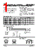
2 / 10 page  Ver: 7.2 Jan 20, 2006 TEL: 886-3-5788833 http://www.gmt.com.tw 2 G910/G911 Global Mixed-mode Technology Inc. Absolute Maximum Ratings (Note 1) Input Voltage. . . . . . . . . . . . . . . . . . . . . . . . . . . . . . . 7V Power Dissipation Internally Limited (Note2) Maximum Junction Temperature . . . . . . . . . . . . .150°C Storage Temperature Range. . . . . -65°C ≤ TJ ≤+150°C Reflow Temperature (soldering, 10sec) . . . . . . .260°C Thermal Resistance Junction to Ambient, (θJA) SOT-89. . . . . . . . . . . . . . . . . . . . . . . . . . . . . 173°C/W(1) SOT-223. . . . . . . . . . . . . . . . . . . . . . . . . . . . 148°C/W(1) µTO-92, TO-92 . . . . . . . . . . . . . . . . . . . . . . .159°C/W(1) Thermal Resistance Junction to Case, (θJc) SOT-89. . . . . . . . . . . . . . . . . . . . . . . . . . . . . . ..25°C/W SOT-223 . . . . . . . . . . . . . . . . . . . . . .. . . . . . . . 22°C/W Note (1): See Recommended Minimum Footprint. Operating Conditions (Note 1) Input Voltage. . . . . . . . . . . . . . . . . . . . . . . . . 4V ~ 6.5V Temperature Range . . . . . . . . . . . . .-40°C ≤ TA ≤85°C Electrical Characteristics VIN =5V, IO = 600mA/250mA+, CIN=10µF, COUT =10µF. All specifications apply for TA = TJ = 25°C.[Note 3] PARAMETER CONDITION MIN TYP MAX UNIT 10mA < IO <600mA Output Voltage 10mA < IO <250mA + 3.234 3.3 3.366 V Line Regulation 4V < VIN < 6V, IO = 10mA --- 15 --- mV 10mA < IO < 600mA --- 20 --- Load Regulation 10mA < IO < 250mA + --- 10 --- mV Quiescent Current VIN = 5V --- 0.3 --- mA Ripple Rejection fi = 120 Hz, 1VP-P, Io = 100mA --- 47 --- dB IO = 600mA --- 0.65 --- Dropout Voltage IO = 250mA + --- 0.25 --- V VIN = 4.5V, mounted on SOT-89 recom- mended minimum footprint --- 600 --- Output Current Continuous Test TA = 25°C, TJ < 125°C, VOUT within ±2% (Note 2) VIN = 5.2V, µTO-92 & TO-92 package 0.53 inch leads soldered to PC Board --- 250+ --- mA Short Circuit Current --- 0.65 --- A Current Limit 0.8 A Over Temperature --- 145 --- °C [ + for µTO-92 & TO-92 Package] Note 1: Absolute Maximum Ratings are limits beyond which damage to the device may occur. Operating Conditions are condi- tions under which the device functions but the specifications might not be guaranteed. For guaranteed specifications and test conditions see the Electrical Characteristics. Note2: The maximum power dissipation is a function of the maximum junction temperature, TJmax ; total thermal resistance, θJA, and ambient temperature TA. The maximum allowable power dissipation at any ambient temperature is Tjmax-TA / θJA. If this dissipation is exceeded, the die temperature will rise above 150°C and IC will go into thermal shutdown. For the G910 in µTO-92, TO-92, θJA is 159°C/W ;in the SOT-223 package is 148°C/W and SOT-89 package is 173°C/W (See Recom- mended Minimum Footprint). The safe operation in TO-92 & µTO-92 package, it can see “Typical Performance Charac- teristics” (Safe Operating Area). Note3: Low duty pulse techniques are used during test to maintain junction temperature as close to ambient as possible. Note4: The type of output capacitor should be tantalum or aluminum. Definitions Dropout Voltage The input/output Voltage differential at which the regu- lator output no longer maintains regulation against further reductions in input voltage. Measured when the output drops 100mV below its nominal value, dropout voltage is affected by junction temperature, load cur- rent and minimum input supply requirements. Line Regulation The change in output voltage for a change in input volt- age. The measurement is made under conditions of low dissipation or by using pulse techniques such that av- erage chip temperature is not significantly affected. Load Regulation The change in output voltage for a change in load current at constant chip temperature. The measure- ment is made under conditions of low dissipation or by using pulse techniques such that average chip tem- perature is not significantly affected. Maximum Power Dissipation The maximum total device dissipation for which the regulator will operate within specifications. Quiescent Bias Current Current which is used to operate the regulator chip and is not delivered to the load. |
|
|
Ligação URL |
| ALLDATASHEET é útil para você? [ DONATE ] |
Sobre Alldatasheet | Publicidade | Contato conosco | Privacy Policy | Link para a ficha técnica | roca de Link | Lista de Fabricantes All Rights Reserved©Alldatasheet.com |
| Russian : Alldatasheetru.com | Korean : Alldatasheet.co.kr | Spanish : Alldatasheet.es | French : Alldatasheet.fr | Italian : Alldatasheetit.com Portuguese : Alldatasheetpt.com | Polish : Alldatasheet.pl | Vietnamese : Alldatasheet.vn Indian : Alldatasheet.in | Mexican : Alldatasheet.com.mx | British : Alldatasheet.co.uk | New Zealand : Alldatasheet.co.nz |
|
Family Site : ic2ic.com |
icmetro.com |
 Portuguese ▼
 English
 Chinese
 German
 Japanese
 Russian
 Korean
 Spanish
 French
 Italian
 Portuguese
 Polish
 Vietnamese
 Indian
 Mexican
 British
 New Zealand