|
Os motores de busca de Datasheet de Componentes eletrônicos |
|
|
Os motores de busca de Datasheet de Componentes eletrônicos |
|
AD820ARMZ-R7 Folha de dados(PDF) 18 Page - Analog Devices |
|
|
|||||||||||||||||||||||||||||
AD820ARMZ-R7 Folha de dados(HTML) 18 Page - Analog Devices |
|
|
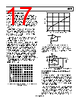
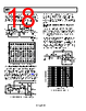
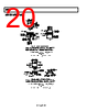
18 / 24 page  AD820 Rev. H | Page 18 of 24 noninverting input of Amplifier A2 sees the ground level output of A1; therefore, A2 operates as a unity-gain inverter. The output at Node C is then a full-wave rectified version of the input. Node B is a buffered half-wave rectified version of the input. Input voltages up to ±18 V can be rectified, depending on the voltage supply used. A1 – + +VS 0.01µF R1 100kΩ R2 100kΩ AD820 FULL-WAVE RECTIFIED OUPUT VIN 3 A C 2 4 7 6 – + – + HALF-WAVE RECTIFIED OUPUT – + B A B C 100 90 10 0% A2 +VS 0.01µF AD820 3 2 4 7 6 Figure 43. Single-Supply Half- and Full-Wave Rectifier 4.5 V LOW DROPOUT, LOW POWER REFERENCE The rail-to-rail performance of the AD820 can be used to provide low dropout performance for low power reference circuits powered with a single low voltage supply. Figure 44 shows a 4.5 V reference using the AD820 and the AD680, a low power 2.5 V band gap reference. R2 and R3 set up the required gain of 1.8 to develop the 4.5 V output. R1 and C2 form a low- pass RC filter to reduce the noise contribution of the AD680. R2 90kΩ (20kΩ) R1 100kΩ R3 100kΩ (25kΩ) U2 AD820 – + 2.5V OUTPUT 4.5V OUTPUT 5V REF COMMON C3 10µF/25V U1 AD680 C2 0.1µF FILM 3 2 4 4 7 6 2 6 3 2.5V ± 10mV C1 0.1µF Figure 44. Single Supply 4.5 V Low Dropout Reference With a 1 mA load, this reference maintains the 4.5 V output with a supply voltage down to 4.7 V. The amplitude of the recovery transient for a 1 mA to 10 mA step change in load current is under 20 mV, and settles out in a few microseconds. Output voltage noise is less than 10 μV rms in a 25 kHz noise bandwidth. LOW POWER, 3-POLE, SALLEN KEY LOW-PASS FILTER The high input impedance of the AD820 makes it a good selection for active filters. High value resistors can be used to construct low frequency filters with capacitors much less than 1 μF. The AD820 picoamp level input currents contribute minimal dc errors. Figure 45 shows an example of a 10 Hz three-pole Sallen Key filter. The high value used for R1 minimizes interaction with signal source resistance. Pole placement in this version of the filter minimizes the Q associated with the two-pole section of the filter. This eliminates any peaking of the noise contribution of Resistor R1, Resistor R2, and Resistor R3, thus minimizing the inherent output voltage noise of the filter. AD820 – + +VS –VS 0.01µF 0.01µF VOUT 3 2 4 7 6 – + R3 243kΩ C3 0.022µF – + VIN R2 243kΩ R1 243kΩ C1 0.022µF C2 0.022µF 0 –100 0.1 1k FREQUENCY (Hz) 1 10 100 –10 –20 –30 –40 –50 –60 –70 –80 –90 Figure 45. 10 Hz Sallen Key Low-Pass Filter |
|
|
Ligação URL |
| ALLDATASHEET é útil para você? [ DONATE ] |
Sobre Alldatasheet | Publicidade | Contato conosco | Privacy Policy | Link para a ficha técnica | roca de Link | Lista de Fabricantes All Rights Reserved©Alldatasheet.com |
| Russian : Alldatasheetru.com | Korean : Alldatasheet.co.kr | Spanish : Alldatasheet.es | French : Alldatasheet.fr | Italian : Alldatasheetit.com Portuguese : Alldatasheetpt.com | Polish : Alldatasheet.pl | Vietnamese : Alldatasheet.vn Indian : Alldatasheet.in | Mexican : Alldatasheet.com.mx | British : Alldatasheet.co.uk | New Zealand : Alldatasheet.co.nz |
|
Family Site : ic2ic.com |
icmetro.com |
 Portuguese ▼
 English
 Chinese
 German
 Japanese
 Russian
 Korean
 Spanish
 French
 Italian
 Portuguese
 Polish
 Vietnamese
 Indian
 Mexican
 British
 New Zealand