|
Os motores de busca de Datasheet de Componentes eletrônicos |
|
|
Os motores de busca de Datasheet de Componentes eletrônicos |
|
27DS-R-PC-CF Folha de dados(PDF) 4 Page - DDK Ltd. |
|
|
|||||||||||||||||||||||||||||
27DS-R-PC-CF Folha de dados(HTML) 4 Page - DDK Ltd. |
|
|
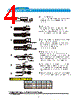
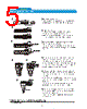
4 / 5 page  Unit:mm http://www.ddknet.co.jp 27DS Series 4 ◎ Specifications and/or dimensions in this catalog are subject to change without notice. Your checking the latest specifications with our drawings would be highly appreciated. ○ Assembly Instruction((1) A Ferrule Outer Conductor Sheath Ferrule B C B C Center Conductor (Pre-soldering) Center Conductor (Pre-soldering) Body end face Contact No gap Soldering Insulator Dies:B Cable Body Assembly Heat-shrinkable tube Heat-shrinkable tube Part Number A B C 27DS-P-1.5-CF 6.4 2.4 1.6 27DS-P-196U-CF 5.4 2.4 1.6 27DS-BJ-1.5-CF 8.0 2.4 2.4 ■ Dimension table interfere 0 -0.4 ① Cut the cable as fig.1. Cut off in the A size from an end face of a cable. Please be careful to not damage the outer conductor. ② Insert Ferrule 1)At 1.5D-2V and 1.5D-QEV, an application cable puts a ferrule in inside outside covering. 2)Application cable is RG-196A/U, a ferrule inserts until bump against covering outside the cable. ④ Soldering of Central Contact Solder up the contact with the center conductor. Please be careful to not deform the insulator by heat. When the solder is stick out, please shave the extra solder. No gap between contact and insulator ofthe cable. Let the cable through the shrinkage tube. ③ Stretched to loosen the cable braid, covers the extent to Trim the outer ferrule wrap. Next Dimension B, C (see Table interfere dimension) so that, except off to adhere to the wound center conductor of the cable insulation. Central Conductor soldered. ⑤ Insert the assembly into the body until it hits those assembled, make sure the position of the contact center. Crimp the edge according to dies assembled body and face as shown on left and then using a special tool. ⑥ To protect a cable attaching portion at the end, please cover, heat and fix heat-shrinkable tubing like a left figure. ① ② ③ ④ ⑤ ⑥ |
|
|
Ligação URL |
| ALLDATASHEET é útil para você? [ DONATE ] |
Sobre Alldatasheet | Publicidade | Contato conosco | Privacy Policy | Link para a ficha técnica | roca de Link | Lista de Fabricantes All Rights Reserved©Alldatasheet.com |
| Russian : Alldatasheetru.com | Korean : Alldatasheet.co.kr | Spanish : Alldatasheet.es | French : Alldatasheet.fr | Italian : Alldatasheetit.com Portuguese : Alldatasheetpt.com | Polish : Alldatasheet.pl | Vietnamese : Alldatasheet.vn Indian : Alldatasheet.in | Mexican : Alldatasheet.com.mx | British : Alldatasheet.co.uk | New Zealand : Alldatasheet.co.nz |
|
Family Site : ic2ic.com |
icmetro.com |
 Portuguese ▼
 English
 Chinese
 German
 Japanese
 Russian
 Korean
 Spanish
 French
 Italian
 Portuguese
 Polish
 Vietnamese
 Indian
 Mexican
 British
 New Zealand