|
Os motores de busca de Datasheet de Componentes eletrônicos |
|
|
Os motores de busca de Datasheet de Componentes eletrônicos |
|
WM8727 Folha de dados(PDF) 9 Page - Wolfson Microelectronics plc |
|
|
|||||||||||||||||||||||||||||
WM8727 Folha de dados(HTML) 9 Page - Wolfson Microelectronics plc |
|
|
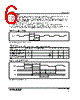
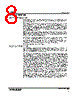
9 / 16 page  WM8727 Production Data w PD Rev 4.1 April 2004 9 CLOCKING SCHEMES In a typical digital audio system there is only one central clock source producing a reference clock to which all audio data processing is synchronised. This clock is often referred to as the audio system’s Master Clock. The external master clock can be applied directly through the MCLK input pin with no configuration necessary for sample rate selection. Note that on the WM8727, MCLK is used to derive clocks for the DAC path. The DAC path consists of DAC sampling clock, DAC digital filter clock and DAC digital audio interface timing. In a system where there are a number of possible sources for the reference clock it is recommended that the clock source with the lowest jitter be used to optimise the performance of the DAC. The device can be powered down by stopping MCLK. In this state the power consumption is substantially reduced. DIGITAL AUDIO INTERFACE Audio data is applied to the internal DAC filters via the Digital Audio Interface. The WM8727 supports the popular I 2S audio interface format. The WM8727 supports word lengths of 16-24 bits (MSB first). The word length may be any value up to 24-bits. (If a word length shorter than 24-bits is used, the unused bits will be padded with zeros). ‘Packed’ mode (i.e. only 32 or 48 clocks per LRCIN period) operation is also supported. If a ‘packed’ format of 16-bit word length is applied (16 BCKINS per LRCIN half period), the device auto-detects this mode and switches to 16-bit data length. The digital audio interface receives data on the DIN input. Audio Data is time multiplexed with LRCIN indicating whether the left or right channel is present. LRCIN is also used as a timing reference to indicate the beginning or end of the data words. The minimum number of BCKINs per LRCIN period is 2 times the selected word length. LRCIN must be high for a minimum of word length BCKINs and low for a minimum of word length BCKINs. Any mark to space ratio on LRCIN is acceptable provided the above requirements are met. In the I 2S mode, the MSB is sampled on the second rising edge of BCKIN following a LRCIN transition. LRCIN is low during the left samples and high during the right samples. LEFT CHANNEL RIGHT CHANNEL LRCIN BCKIN DIN 1/fs n 3 2 1 n-2 n-1 LSB MSB n 3 2 1 n-2 n-1 LSB MSB 1 BCKIN 1 BCKIN Figure 3 I 2S Mode Timing Diagram |
|
|
Ligação URL |
| ALLDATASHEET é útil para você? [ DONATE ] |
Sobre Alldatasheet | Publicidade | Contato conosco | Privacy Policy | Link para a ficha técnica | roca de Link | Lista de Fabricantes All Rights Reserved©Alldatasheet.com |
| Russian : Alldatasheetru.com | Korean : Alldatasheet.co.kr | Spanish : Alldatasheet.es | French : Alldatasheet.fr | Italian : Alldatasheetit.com Portuguese : Alldatasheetpt.com | Polish : Alldatasheet.pl | Vietnamese : Alldatasheet.vn Indian : Alldatasheet.in | Mexican : Alldatasheet.com.mx | British : Alldatasheet.co.uk | New Zealand : Alldatasheet.co.nz |
|
Family Site : ic2ic.com |
icmetro.com |
 Portuguese ▼
 English
 Chinese
 German
 Japanese
 Russian
 Korean
 Spanish
 French
 Italian
 Portuguese
 Polish
 Vietnamese
 Indian
 Mexican
 British
 New Zealand