|
Os motores de busca de Datasheet de Componentes eletrônicos |
|
|
Os motores de busca de Datasheet de Componentes eletrônicos |
|
IM802B Folha de dados(PDF) 5 Page - ILSI America LLC |
|
|
|||||||||||||||||||||||||||||
IM802B Folha de dados(HTML) 5 Page - ILSI America LLC |
|
|
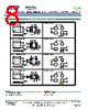
5 / 9 page  MEMS Oscillator, Low Power, LVCMOS/HCMOS Compatible, 115.000 MHz to 137.000 MHz IM802 Series ILSI America Phone 775-851-8880 ● Fax 775-851-8882 ●email: e-mail@ilsiamerica.com ● www.ilsiamerica.com Specifications subject to change without notice Rev: 01/30/16_A Page 5 of 9 Pin Functionally Pin Description Pin Symbol Functionality Pin Assignments 1 OE Tri-state High or Open = specified frequency output Low = Output is high impedance, only output is disabled. 14 3 2 Top View GND Vdd OUT OE ST N/C ST Standby High or Open = specified frequency output. Low = Output is low. Device goes to sleep mode. Supply current reduces to standby current. N/C No Connect Any voltage between 0.0 V to Vdd or Open = specified frequency output Pin 1 has no functiion 2 GND Power Electrical ground 3 Out Output Oscillator output 4 Vdd Power Power supply voltage Notes: 1. In OE or ST mode, a pull-up resistor of 10.0 kΩ or less is recommended if Pin 1 is not externally driven. If Pin 1 needs to be left floating, use the NC option. 2. A capacitor of value 0.1 µF or higher between Pin 4 (Vdd) and Pin 1 (GND) is required. Pin 1 Configuration Options (OE, or , or NC) Pin 1 of the IM802 can be factory-programmed to support three modes: Output Enable (OE), Standby (ST) or No Connect (NC). Output Enable (OE) Mode In the OE mode, applying logic Low to the OE pin only disables the output driver and puts it in Hi-Z mode. The core of the device continues to operate normally. Power consumption is reduced due to the inactivity of the output. When the OE pin is pulled High, the output is typically enabled in <1 µSec. Standby Mode In the ST mode, a device enters into the standby mode when Pin 1 pulled Low. All internal circuits of the device are turned off. The current is reduced to a standby current, typically in the range of a few µA. When ST is pulled High, the device goes through the “resume” process, which can take up to 5 mSec. No Connect (NC) Mode In the NC mode, the device always operates in its normal mode and outputs the specified frequency regardless of the logic level on Pin 1. Table 1 below summarizes the key relevant parameters in the operation of the device in OE, ST, or NC mode. Parameters OE ST NC Active current 125.0 MHz (max +1.80 VDC) 5.6 mA 5.6 mA 5.6 mA OE disable current (max +1.80 VDC) 4.0 mA N/A N/A Standby current (typical +1.80 VDC) N/A 0.6 µA N/A OE enable time at 125.0 MHz (max) 124 nSec N/A N/A Resume time from standby (max, all frequency) N/A 5 mSec N/A Output driver in OE disable/standby mode High Z N/A Table 1 OE vs. ST vs. NC |
|
|
Ligação URL |
| ALLDATASHEET é útil para você? [ DONATE ] |
Sobre Alldatasheet | Publicidade | Contato conosco | Privacy Policy | Link para a ficha técnica | roca de Link | Lista de Fabricantes All Rights Reserved©Alldatasheet.com |
| Russian : Alldatasheetru.com | Korean : Alldatasheet.co.kr | Spanish : Alldatasheet.es | French : Alldatasheet.fr | Italian : Alldatasheetit.com Portuguese : Alldatasheetpt.com | Polish : Alldatasheet.pl | Vietnamese : Alldatasheet.vn Indian : Alldatasheet.in | Mexican : Alldatasheet.com.mx | British : Alldatasheet.co.uk | New Zealand : Alldatasheet.co.nz |
|
Family Site : ic2ic.com |
icmetro.com |
 Portuguese ▼
 English
 Chinese
 German
 Japanese
 Russian
 Korean
 Spanish
 French
 Italian
 Portuguese
 Polish
 Vietnamese
 Indian
 Mexican
 British
 New Zealand