|
Os motores de busca de Datasheet de Componentes eletrônicos |
|
|
Os motores de busca de Datasheet de Componentes eletrônicos |
|
PA02 Folha de dados(PDF) 4 Page - Cirrus Logic |
|
|
|||||||||||||||||||||||||||||
PA02 Folha de dados(HTML) 4 Page - Cirrus Logic |
|
|
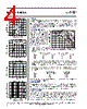
4 / 4 page  APEX MICROTECHNOLOGY CORPORATION • 5980 NORTH SHANNON ROAD • TUCSON, ARIZONA 85741 • USA • APPLICATIONS HOTLINE: 1 (800) 546-2739 4 OPERATING CONSIDERATIONS PA02 • PA02A GENERAL Please read Application Note 1 "General Operating Considerations" which cov- ers stability, supplies, heat sinking, mounting, current limit, SOA interpretation, and specification interpretation. Visit www.apexmicrotech.com for design tools that help automate tasks such as calculations for stability, internal power dissipation, current limit; heat sink selection; Apex’s complete Application Notes library; Technical Seminar Workbook; and Evaluation Kits. SAFE OPERATING AREA The SOA curves combine the effect of all limits for this Power Op Amp. For a given application, the direction and magnitude of the output current should be cal- culated or measured and checked against the SOA curves. This is simple for resistive loads but more complex for reactive and EMF generating loads. The following guidelines may save extensive analytical efforts: 1. Under transient conditions, capacitive and dynamic* loads up to the following maximums are safe: CAPACITIVE LOAD INDUCTIVE LOAD ±V S I LIM = 2A I LIM = 5A I LIM = 2A I LIM = 5A 18V 2mF 0.7mF .2H 10mH 15V 10mF 2.2mF .7H 25mH 10V 25mF 10mF 5H 50mH * If the inductive load is driven near steady state conditions, allowing the output voltage to drop more than 8V below the supply rail with I LIM = 5A, or 17V below the supply rail with I LIM = 2A while the amplifier is current limiting, the inductor should be capacitively coupled or the current limit must be lowered to meet SOA criteria. 2. The amplifier can handle any EMF generating or reactive load and short circuits to the supply rails or shorts to common if the current limits are set as follows at T C = 85°C. SHORT TO ±V S SHORT TO ±V S C, L OR EMF LOAD COMMON 18V .5A 1.7A 15V .7A 2.8A 10V 1.6A 4.2A These simplified limits may be exceeded with further analysis using the operating conditions for a specific application. CURRENT LIMIT Proper operation requires the use of two current limit resistors, connected as shown in the external connection diagram. The minimum value for R CL is 0.12 ohm, however for optimum reliability it should be set as high as possible. Refer to the “General Operating Considerations” section of the handbook for current limit adjust details. DEVICE MOUNTING The case (mounting flange) is electrically isolated and should be mounted directly to a heatsink with thermal compound. Screws with Belville spring washers are recommended to maintain positive clamping pressure on heatsink mounting surfaces. Long periods of thermal cycling can loosen mounting screws and increase thermal resistance. Since the case is electrically isolated (floating) with respect to the internal circuits it is recommended to connect it to common or other convenient AC ground potential. � � � � �� �� �� �� �� �� ��� ��� ��� ��� ��� ��� ��� ��� ��� ��� ������������������������������������������������ ������� � � ������ �� � � ������� � � ����� �� � � ������ �� ��� ��� �� �� ��� ����������������� ���� �� � ������������������� ���� ��� �� ��� ��� ��� ��� ��� � � � ������������ ��� � �� �������������� ��� � �� � � �� �������������� ��� ��� � �� �� �� ��� ��� ����������������� ��������������� ���� ��� � ��� ��� �� ���� ��� ��� ������������ � �� ��� ��� � �������� ���������� � ����� � � ������ � � ����� � �������������������� � �������������������� ������������� � ��������� � ��������� This data sheet has been carefully checked and is believed to be reliable, however, no responsibility is assumed for possible inaccuracies or omissions. All specifications are subject to change without notice. PA02U REV. L FEBRUARY 1998 © 1998 Apex Microtechnology Corp. |
|
|
Ligação URL |
| ALLDATASHEET é útil para você? [ DONATE ] |
Sobre Alldatasheet | Publicidade | Contato conosco | Privacy Policy | Link para a ficha técnica | roca de Link | Lista de Fabricantes All Rights Reserved©Alldatasheet.com |
| Russian : Alldatasheetru.com | Korean : Alldatasheet.co.kr | Spanish : Alldatasheet.es | French : Alldatasheet.fr | Italian : Alldatasheetit.com Portuguese : Alldatasheetpt.com | Polish : Alldatasheet.pl | Vietnamese : Alldatasheet.vn Indian : Alldatasheet.in | Mexican : Alldatasheet.com.mx | British : Alldatasheet.co.uk | New Zealand : Alldatasheet.co.nz |
|
Family Site : ic2ic.com |
icmetro.com |
 Portuguese ▼
 English
 Chinese
 German
 Japanese
 Russian
 Korean
 Spanish
 French
 Italian
 Portuguese
 Polish
 Vietnamese
 Indian
 Mexican
 British
 New Zealand