|
Os motores de busca de Datasheet de Componentes eletrônicos |
|
|
Os motores de busca de Datasheet de Componentes eletrônicos |
|
UCD3138064RGCT Folha de dados(PDF) 71 Page - Texas Instruments |
|
|
|
|||||||||||||||||||||||||||||
UCD3138064RGCT Folha de dados(HTML) 71 Page - Texas Instruments |
|
|
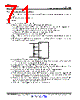
71 / 91 page  2 .2 F 1 .0 F BP18 DGND V33D UCD3138064 www.ti.com SLUSB72B – MARCH 2013 – REVISED SEPTEMBER 2014 7.2.4 Power Supply Recommendations • Both 3.3 VD and 3.3 VA should have a local 4.7-µF capacitor placed as close as possible to the device pins • BP18 should have a 1-µF capacitor. 7.2.5 Layout 7.2.5.1 IC Grounding and Layout Guidelines • Two grounds are recommended: AGND (analog) and DGND (digital). – AGND plane should be on a different layer than DGND, and right under the UCD3138064 device. – UCD3138064 power pad should be tied to AGND plane by at least 4 vias – AGND plane should be just large enough to connect to all required components. – Power ground (PGND) can be independent or combined with DGND – The power pad of the driver IC should be tied to DGND • Both 3.3VD and 3.3VA should have a local 4.7µF capacitor placed as close as possible to the device pins • BPCAP decoupling MUST be connected as shown in the following figure. It is important that the ratio of the 2.2-µF to 1.0-µF capacitor be 2.2:1. • All analog signal filter capacitors should be tied to AGND – If the gate driver device, such as UCD27524 or UCD27511/7 driver is used, the filter capacitor for the current sensing pin can be tied to DGND for easy layout • All digital signals, such as GPIO, PMBus and PWM are referenced to DGND. • The RESET pin capacitor (at least 0.1 µF) should be connected to either DGND or AGND locally. If the RESET pin is unused it is recommended to tie the pin directly to 3.3V. • All filter and decoupling capacitors should be placed close to UCD3138064 as possible – Resistor placement is less critical and can be moved a little further away • The DGND and AGND net-short resistor MUST be placed right between one UCD3138064’s DGND pin and one AGND pin. Ground connections to the net short element should be made by a large via (or multiple paralleled vias) for each terminal of the net-short element. • If a gate driver device such as UCC27524 or UCC27511/7 is on the control card and there is a PGND connection, a net-short resistor should be tied to the DGND plane and PGND plane by multiple vias. In addition the net-short element should be close to the driver IC. • Configure all unused GPIO as inputs and connect them to ground. Copyright © 2013–2014, Texas Instruments Incorporated Applications, Implementation, and Layout 71 Submit Documentation Feedback Product Folder Links: UCD3138064 |
|
Ligação URL |
| ALLDATASHEET é útil para você? [ DONATE ] |
Sobre Alldatasheet | Publicidade | Contato conosco | Privacy Policy | Link para a ficha técnica | roca de Link | Lista de Fabricantes All Rights Reserved©Alldatasheet.com |
| Russian : Alldatasheetru.com | Korean : Alldatasheet.co.kr | Spanish : Alldatasheet.es | French : Alldatasheet.fr | Italian : Alldatasheetit.com Portuguese : Alldatasheetpt.com | Polish : Alldatasheet.pl | Vietnamese : Alldatasheet.vn Indian : Alldatasheet.in | Mexican : Alldatasheet.com.mx | British : Alldatasheet.co.uk | New Zealand : Alldatasheet.co.nz |
|
Family Site : ic2ic.com |
icmetro.com |
 Portuguese ▼
 English
 Chinese
 German
 Japanese
 Russian
 Korean
 Spanish
 French
 Italian
 Portuguese
 Polish
 Vietnamese
 Indian
 Mexican
 British
 New Zealand