|
Os motores de busca de Datasheet de Componentes eletrônicos |
|
|
Os motores de busca de Datasheet de Componentes eletrônicos |
|
UCD3138064RGCR Folha de dados(PDF) 39 Page - Texas Instruments |
|
|
|
|||||||||||||||||||||||||||||
UCD3138064RGCR Folha de dados(HTML) 39 Page - Texas Instruments |
|
|
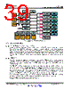
39 / 91 page  Digital Comparator 0 Control Digital Comparator 1 Control Digital Comparator 2 Control Digital Comparator 3 Control Front End Control 0 Front End Control 1 Front End Control 2 Analog Comparator 0 Analog Comparator 0 Control Analog Comparator 1 Analog Comparator 1 Control Analog Comparator 2 Analog Comparator 2 Control Analog Comparator 3 Analog Comparator 3 Control Analog Comparator 4 Analog Comparator 4 Control Analog Comparator 5 Analog Comparator 5 Control Analog Comparator 6 Analog Comparator 6 Control External GPIO Detection fault[2:0] DPWM 0 DPWM 1 DPWM 2 DPWM 3 DPWM 0 Fault Control DPWM 1 Fault Control DPWM 2 Fault Control DPWM 3 Fault Control Analog Comparator Automated Ramp DCM Detection HFO/LFO Fail Detect UCD3138064 www.ti.com SLUSB72B – MARCH 2013 – REVISED SEPTEMBER 2014 Figure 6-16. Fault Mux Block Diagram 6.3.6 Communication Ports 6.3.6.1 SCI (UART) Serial Communication Interface A maximum of two independent Serial Communication Interface (SCI) or Universal Asynchronous Receiver/Transmitter (UART) interfaces are included within the device for asynchronous start-stop serial data communication (see the pin out sections for details). Each interface has a 24 bit pre-scaler for supporting programmable baud rates, a programmable data word and stop bit options. Half or full duplex operation is configurable through register bits. A loop back feature can also be setup for firmware verification. Both SCI-TX and SCI-RX pin sets can be used as GPIO pins when the peripheral is not being used. 6.3.6.2 PMBUS/I2C The UCD3138x has two independent interfaces which both support PMBus and I2C in master and slave modes. Only one of the interfaces has control of the address pin current sources as well as support for the optional Control and Alert lines described in the PMBus specification. Other than these differences, the interfaces are identical. The PMBus/I2C interface is designed to minimize the processor overhead required for interface. It can automatically detect and acknowledge addresses. It handles start and stop conditions automatically, and can clock stretch until the processor has time to poll the PMBus status. It will automatically receive and send up to 4 bytes at a time. It can automatically verify and generate a PEC. This means that a write byte command can be received by the processor with only one function call. There is no need for any interrupts at all with this PMBus/I2C interface. If it is polled every few milliseconds, it will work perfectly. The interface also supports automatic ACK of two independent addresses. If both PMBus/I2C interfaces are used at the same time a total of 4 independent addresses can be automatically detected. Example: PMBus Address Decode via ADC12 Reading Copyright © 2013–2014, Texas Instruments Incorporated Detailed Description 39 Submit Documentation Feedback Product Folder Links: UCD3138064 |
|
Ligação URL |
| ALLDATASHEET é útil para você? [ DONATE ] |
Sobre Alldatasheet | Publicidade | Contato conosco | Privacy Policy | Link para a ficha técnica | roca de Link | Lista de Fabricantes All Rights Reserved©Alldatasheet.com |
| Russian : Alldatasheetru.com | Korean : Alldatasheet.co.kr | Spanish : Alldatasheet.es | French : Alldatasheet.fr | Italian : Alldatasheetit.com Portuguese : Alldatasheetpt.com | Polish : Alldatasheet.pl | Vietnamese : Alldatasheet.vn Indian : Alldatasheet.in | Mexican : Alldatasheet.com.mx | British : Alldatasheet.co.uk | New Zealand : Alldatasheet.co.nz |
|
Family Site : ic2ic.com |
icmetro.com |
 Portuguese ▼
 English
 Chinese
 German
 Japanese
 Russian
 Korean
 Spanish
 French
 Italian
 Portuguese
 Polish
 Vietnamese
 Indian
 Mexican
 British
 New Zealand