|
Os motores de busca de Datasheet de Componentes eletrônicos |
|
|
Os motores de busca de Datasheet de Componentes eletrônicos |
|
PIC18F2680ISOSQTP Folha de dados(PDF) 261 Page - Microchip Technology |
|
|
|||||||||||||||||||||||||||||
PIC18F2680ISOSQTP Folha de dados(HTML) 261 Page - Microchip Technology |
|
|
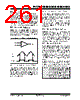
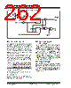
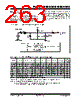
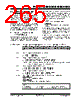
261 / 482 page  © 2007 Microchip Technology Inc. Preliminary DS39625C-page 259 PIC18F2585/2680/4585/4680 20.2 Comparator Operation A single comparator is shown in Figure 20-2, along with the relationship between the analog input levels and the digital output. When the analog input at VIN+ is less than the analog input VIN-, the output of the comparator is a digital low level. When the analog input at VIN+ is greater than the analog input VIN-, the output of the comparator is a digital high level. The shaded areas of the output of the comparator in Figure 20-2 represent the uncertainty, due to input offsets and response time. 20.3 Comparator Reference Depending on the comparator operating mode, either an external or internal voltage reference may be used. The analog signal present at VIN- is compared to the signal at VIN+ and the digital output of the comparator is adjusted accordingly (Figure 20-2). FIGURE 20-2: SINGLE COMPARATOR 20.3.1 EXTERNAL REFERENCE SIGNAL When external voltage references are used, the comparator module can be configured to have the com- parators operate from the same or different reference sources. However, threshold detector applications may require the same reference. The reference signal must be between VSS and VDD and can be applied to either pin of the comparator(s). 20.3.2 INTERNAL REFERENCE SIGNAL The comparator module also allows the selection of an internally generated voltage reference from the comparator voltage reference module. This module is described in more detail in Section 21.0 “Comparator Voltage Reference Module”. The internal reference is only available in the mode where four inputs are multiplexed to two comparators (CM2:CM0 = 110). In this mode, the internal voltage reference is applied to the VIN+ pin of both comparators. 20.4 Comparator Response Time Response time is the minimum time, after selecting a new reference voltage or input source, before the comparator output has a valid level. If the internal reference is changed, the maximum delay of the internal voltage reference must be considered when using the comparator outputs. Otherwise, the maximum delay of the comparators should be used (see Section 27.0 “Electrical Characteristics”). 20.5 Comparator Outputs The comparator outputs are read through the CMCON register. These bits are read-only. The comparator outputs may also be directly output to the RE1 and RE2 I/O pins. When enabled, multiplexors in the output path of the RE1 and RE2 pins will switch and the output of each pin will be the unsynchronized output of the comparator. The uncertainty of each of the comparators is related to the input offset voltage and the response time given in the specifications. Figure 20-3 shows the comparator output block diagram. The TRISE bits will still function as an output enable/ disable for the RE1 and RE2 pins while in this mode. The polarity of the comparator outputs can be changed using the C2INV and C1INV bits (CMCON<4:5>). – + VIN + VIN - Output Output VIN- VIN+ Note 1: When reading the Port register, all pins configured as analog inputs will read as a ‘0’. Pins configured as digital inputs will convert an analog input according to the Schmitt Trigger input specification. 2: Analog levels on any pin defined as a digital input may cause the input buffer to consume more current than is specified. |
|
Ligação URL |
| ALLDATASHEET é útil para você? [ DONATE ] |
Sobre Alldatasheet | Publicidade | Contato conosco | Privacy Policy | Link para a ficha técnica | roca de Link | Lista de Fabricantes All Rights Reserved©Alldatasheet.com |
| Russian : Alldatasheetru.com | Korean : Alldatasheet.co.kr | Spanish : Alldatasheet.es | French : Alldatasheet.fr | Italian : Alldatasheetit.com Portuguese : Alldatasheetpt.com | Polish : Alldatasheet.pl | Vietnamese : Alldatasheet.vn Indian : Alldatasheet.in | Mexican : Alldatasheet.com.mx | British : Alldatasheet.co.uk | New Zealand : Alldatasheet.co.nz |
|
Family Site : ic2ic.com |
icmetro.com |
 Portuguese ▼
 English
 Chinese
 German
 Japanese
 Russian
 Korean
 Spanish
 French
 Italian
 Portuguese
 Polish
 Vietnamese
 Indian
 Mexican
 British
 New Zealand