|
Os motores de busca de Datasheet de Componentes eletrônicos |
|
|
Os motores de busca de Datasheet de Componentes eletrônicos |
|
LTC3602EFE Folha de dados(PDF) 8 Page - Linear Technology |
|
|
|||||||||||||||||||||||||||||
LTC3602EFE Folha de dados(HTML) 8 Page - Linear Technology |
|
|
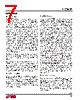
8 / 20 page  LTC3602 8 3602fb OPERATION Dropout Operation When the input supply voltage decreases toward the output voltage, the duty cycle increases toward the maximum on-time. Further reduction of the supply voltage forces the top switch to remain on for more than one cycle until it attempts to stay on continuously. In order to replenish the voltage on the floating BOOST supply capacitor, however, the top switch is forced off and the bottom switch is forced on for approximately 85ns every sixteen clock cycles. This achieves an effective duty cycle that can exceed 99%. The output voltage will then be primarily determined by the input voltage minus the voltage drop across the upper internal N-channel MOSFET and the inductor. Slope Compensation and Inductor Peak Current Slope compensation provides stability in constant-fre- quency architectures by preventing subharmonic oscilla- tions at duty cycles greater than 50%. It is accomplished internally by adding a compensating ramp to the inductor current signal at duty cycles in excess of 30%. Normally, the maximum inductor peak current is reduced when slope compensation is added. In the LTC3602, however, slope compensation recovery is implemented to reduce the variation of the maximum inductor peak current (and therefore the maximum available output current) over the range of duty cycles. Short-Circuit Protection When the output is shorted to ground, the inductor cur- rent decays very slowly during a single switching cycle. To prevent current runaway from occurring, a secondary current limit is imposed on the inductor current. If the inductor valley current increases to more than 4.5A, the top power MOSFET will be held off and switching cycles will be skipped until the inductor current is reduced. Overtemperature Protection When using the LTC3602 in an application circuit, care must be taken not to exceed any of the ratings speci- fied in the Absolute Maximum Ratings section. As an added safeguard, however, the LTC3602 does incorporate an overtemperature shutdown feature. If the junction temperature reaches approximately 150°C, both power switches will be turned off and the SW node will become high impedance. After the part has cooled to below 115°C, it will restart. Voltage Tracking and Soft-Start Some microprocessors and DSP chips need two power supplies with different voltage levels. These systems often require voltage sequencing between the core power supply and the I/O power supply. Without proper sequencing, latch-up failure or excessive current draw may occur that could result in damage to the processor’s I/O ports or the I/O ports of a supporting system device such as memory, an FPGA or a data converter. To ensure that the I/O loads are not driven until the core voltage is properly biased, tracking of the core supply and the I/O supply voltage is necessary. Voltage tracking is enabled by applying a ramp voltage to the TRACK/SS pin. When the voltage on the TRACK pin is below 0.6V, the feedback voltage will regulate to this tracking voltage. When the tracking voltage exceeds 0.6V, tracking is disabled and the feedback voltage will regulate to the internal reference voltage. The TRACK/SS pin is also used to implement an external soft-start function. A 1.2μA current is sourced from this pin so that an external capacitor may be added to create a smooth ramp. If this ramp is slower than the internal 1ms soft-start, then the output voltage will track this ramp during start up instead. Leave this pin floating to use the internal 1ms soft-start ramp. Do not tie the TRACK/SS pin to INTVCC or to PVIN. |
|
|
Ligação URL |
| ALLDATASHEET é útil para você? [ DONATE ] |
Sobre Alldatasheet | Publicidade | Contato conosco | Privacy Policy | Link para a ficha técnica | roca de Link | Lista de Fabricantes All Rights Reserved©Alldatasheet.com |
| Russian : Alldatasheetru.com | Korean : Alldatasheet.co.kr | Spanish : Alldatasheet.es | French : Alldatasheet.fr | Italian : Alldatasheetit.com Portuguese : Alldatasheetpt.com | Polish : Alldatasheet.pl | Vietnamese : Alldatasheet.vn Indian : Alldatasheet.in | Mexican : Alldatasheet.com.mx | British : Alldatasheet.co.uk | New Zealand : Alldatasheet.co.nz |
|
Family Site : ic2ic.com |
icmetro.com |
 Portuguese ▼
 English
 Chinese
 German
 Japanese
 Russian
 Korean
 Spanish
 French
 Italian
 Portuguese
 Polish
 Vietnamese
 Indian
 Mexican
 British
 New Zealand