|
Os motores de busca de Datasheet de Componentes eletrônicos |
|
|
Os motores de busca de Datasheet de Componentes eletrônicos |
|
AD830JRZ-R7 Folha de dados(PDF) 17 Page - Analog Devices |
|
|
|||||||||||||||||||||||||||||
AD830JRZ-R7 Folha de dados(HTML) 17 Page - Analog Devices |
|
|
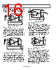
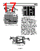
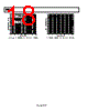
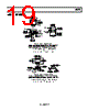
17 / 20 page  AD830 Rev. C | Page 17 of 20 75 Ω 75 Ω VP VOUT VN AD830 1 2 3 4 8 7 6 5 A = 1 GM GM C 0.1µF 0.1µF VIN Figure 44. Full Bandwidth Line Driver (G = +2) SUPPLY VOLTAGE (±V) 0.05 0.01 5 1 5 1 2 1 73 1 0.04 0.06 0.07 0.09 4 GAIN PHASE GAIN = +2 RL = 150Ω FREQ = 3.58MHz 0 TO 0.7V 11 10 9 8 6 0.02 0.03 0.10 0.08 0.16 0.04 0.06 0.14 0.18 0.02 0.12 0.10 0.08 0.20 FREQUENCY (Hz) 0.2 10k –0.8 100k 1M 10M 100M –0.7 –0.6 –0.5 –0.4 –0.3 –0.2 –0.1 0 0.1 VS = ±15V RL = 150Ω GAIN = +2 VS = ±10V VS = ±5V Figure 46. 0.1 dB Gain Flatness for the Circuit of Figure 44 AC-COUPLED LINE RECEIVER The AD830 is configurable as an ac-coupled differential amplifier on a single- or bipolar-supply voltage. All that is needed is inclusion of a few noncritical passive components, as illustrated in Figure 47. A simple resistive network at the X GM input establishes a common-mode bias. Here, the common mode is centered at 6 V, but in principle can be any voltage within the common-mode limits of the AD830. The 10 kΩ resistors to each input bias the X GM stage with sufficiently high impedance to keep the input coupling corner frequency low, but not too large so that residual bias current induced offset voltage becomes troublesome. For dual-supply operation, the 10 kΩ resistors may go directly to ground. The output common is conveniently set by a Zener diode for a low impedance reference to preserve the high frequency CMR. However, a simple resistive divider works fine, and good high frequency CMR can be maintained by placing a compensating resistor in series with the +Y input. The excellent CMRR response of the circuit is shown in Figure 48. A plot of the 0.1 dB flatness from 10 Hz is also shown. With the use of 10 μF capacitors, the CMR is >90 dB down to a few tens of hertz. This level of performance is almost impossible to achieve with discrete solutions. Figure 45. Differential Gain and Phase for the Circuit of Figure 44 75 Ω 75 Ω +12V VOUT 1000µF 10µF 10µF AD830 1 2 3 4 8 7 6 5 A = 1 GM GM C 0.1µF ZCM 75 Ω COAX CABLE +12V 4.7k Ω 6.8V 1N4736 INPUT SIGNAL RT 10k Ω 10k Ω 2k Ω* +VS 10k Ω 10k Ω *OPTIONAL TUNING FOR IMPROVING VERY LOW FREQUENCY CMR. Figure 47. AC-Coupled Line Receiver |
|
|
Ligação URL |
| ALLDATASHEET é útil para você? [ DONATE ] |
Sobre Alldatasheet | Publicidade | Contato conosco | Privacy Policy | Link para a ficha técnica | roca de Link | Lista de Fabricantes All Rights Reserved©Alldatasheet.com |
| Russian : Alldatasheetru.com | Korean : Alldatasheet.co.kr | Spanish : Alldatasheet.es | French : Alldatasheet.fr | Italian : Alldatasheetit.com Portuguese : Alldatasheetpt.com | Polish : Alldatasheet.pl | Vietnamese : Alldatasheet.vn Indian : Alldatasheet.in | Mexican : Alldatasheet.com.mx | British : Alldatasheet.co.uk | New Zealand : Alldatasheet.co.nz |
|
Family Site : ic2ic.com |
icmetro.com |
 Portuguese ▼
 English
 Chinese
 German
 Japanese
 Russian
 Korean
 Spanish
 French
 Italian
 Portuguese
 Polish
 Vietnamese
 Indian
 Mexican
 British
 New Zealand