|
Os motores de busca de Datasheet de Componentes eletrônicos |
|
|
Os motores de busca de Datasheet de Componentes eletrônicos |
|
PIC16C712 Folha de dados(PDF) 81 Page - Microchip Technology |
|
|
|||||||||||||||||||||||||||||
PIC16C712 Folha de dados(HTML) 81 Page - Microchip Technology |
|
|
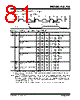
81 / 106 page  1999-2013 Microchip Technology Inc. DS41106C-page 81 PIC16C712/716 12.4.3 TIMING DIAGRAMS AND SPECIFICATIONS FIGURE 12-4: EXTERNAL CLOCK TIMING TABLE 12-2: EXTERNAL CLOCK TIMING REQUIREMENTS Param No. Sym. Characteristic Min. Typ† Max. Units Conditions 1A FOSC External CLKIN Frequency (Note 1) DC — 4 MHz RC and XT osc modes DC — 4 MHz HS osc mode (-04) DC — 20 MHz HS osc mode (-20) DC — 200 kHz LP osc mode Oscillator Frequency (Note 1) DC — 4 MHz RC osc mode 0.1 — 4 MHz XT osc mode 4 — 20 MHz HS osc mode 5 — 200 kHz LP osc mode 1TOSC External CLKIN Period (Note 1) 250 — — ns RC and XT osc modes 250 — — ns HS osc mode (-04) 50 — — ns HS osc mode (-20) 5— — s LP osc mode Oscillator Period (Note 1) 250 — — ns RC osc mode 250 — 10,000 ns XT osc mode 250 — 250 ns HS osc mode (-04) 50 — 250 ns HS osc mode (-20) 5— — s LP osc mode 2 TCY Instruction Cycle Time (Note 1) 200 — DC ns TCY = 4/FOSC 3* TosL, TosH External Clock in (OSC1) High or Low Time 100 — — ns XT oscillator 2.5 — — s LP oscillator 15 — — ns HS oscillator 4* TosR, TosF External Clock in (OSC1) Rise or Fall Time — — 25 ns XT oscillator — — 50 ns LP oscillator — — 15 ns HS oscillator * These parameters are characterized but not tested. † Data in “Typ” column is at 5V, 25°C unless otherwise stated. These parameters are for design guidance only and are not tested. Note1: Instruction cycle period (TCY) equals four times the input oscillator time base period. All specified values are based on characterization data for that particular oscillator type under standard operating conditions with the device executing code. Exceeding these specified limits may result in an unstable oscillator operation and/or higher than expected current consumption. All devices are tested to operate at “min.” values with an external clock applied to the OSC1/CLKIN pin. When an external clock input is used, the “Max.” cycle time limit is “DC” (no clock) for all devices. 3 3 4 4 1 2 Q4 Q1 Q2 Q3 Q4 Q1 OSC1 CLKOUT |
|
Ligação URL |
| ALLDATASHEET é útil para você? [ DONATE ] |
Sobre Alldatasheet | Publicidade | Contato conosco | Privacy Policy | Link para a ficha técnica | roca de Link | Lista de Fabricantes All Rights Reserved©Alldatasheet.com |
| Russian : Alldatasheetru.com | Korean : Alldatasheet.co.kr | Spanish : Alldatasheet.es | French : Alldatasheet.fr | Italian : Alldatasheetit.com Portuguese : Alldatasheetpt.com | Polish : Alldatasheet.pl | Vietnamese : Alldatasheet.vn Indian : Alldatasheet.in | Mexican : Alldatasheet.com.mx | British : Alldatasheet.co.uk | New Zealand : Alldatasheet.co.nz |
|
Family Site : ic2ic.com |
icmetro.com |
 Portuguese ▼
 English
 Chinese
 German
 Japanese
 Russian
 Korean
 Spanish
 French
 Italian
 Portuguese
 Polish
 Vietnamese
 Indian
 Mexican
 British
 New Zealand