|
Os motores de busca de Datasheet de Componentes eletrônicos |
|
|
Os motores de busca de Datasheet de Componentes eletrônicos |
|
AD9764 Folha de dados(PDF) 10 Page - Analog Devices |
|
|
|||||||||||||||||||||||||||||
AD9764 Folha de dados(HTML) 10 Page - Analog Devices |
|
|
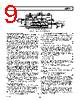
10 / 22 page  REV. B AD9764 –10– REFERENCE OPERATION The AD9764 contains an internal 1.20 V bandgap reference that can be easily disabled and overridden by an external reference. REFIO serves as either an input or output, depending on whether the internal or external reference is selected. If REFLO is tied to ACOM, as shown in Figure 22, the internal reference is activated, and REFIO provides a 1.20 V output. In this case, the internal reference must be compensated externally with a ceramic chip capacitor of 0.1 µF or greater from REFIO to REFLO. Also, REFIO should be buffered with an external amplifier having an input bias current less than 100 nA if any additional loading is required. 50pF COMP1 +1.2V REF AVDD REFLO CURRENT SOURCE ARRAY 0.1 F +5V REFIO FS ADJ 2k 0.1 F AD9764 ADDITIONAL LOAD OPTIONAL EXTERNAL REF BUFFER Figure 22. Internal Reference Configuration The internal reference can be disabled by connecting REFLO to AVDD. In this case, an external reference may then be applied to REFIO as shown in Figure 23. The external reference may provide either a fixed reference voltage to enhance accuracy and drift performance or a varying reference voltage for gain control. Note that the 0.1 µF compensation capacitor is not required since the internal reference is disabled, and the high input im- pedance (i.e., 1 M Ω) of REFIO minimizes any loading of the external reference. 50pF COMP1 +1.2V REF AVDD REFLO CURRENT SOURCE ARRAY 0.1 F AVDD REFIO FS ADJ RSET AD9764 EXTERNAL REF IREF = VREFIO/RSET AVDD REFERENCE CONTROL AMPLIFIER VREFIO Figure 23. External Reference Configuration REFERENCE CONTROL AMPLIFIER The AD9764 also contains an internal control amplifier that is used to regulate the DAC’s full-scale output current, IOUTFS. The control amplifier is configured as a V-I converter, as shown in Figure 23, such that its current output, IREF, is determined by the ratio of the VREFIO and an external resistor, RSET, as stated in Equation 4. IREF is copied over to the segmented current sources with the proper scaling factor to set IOUTFS as stated in Equation 3. The control amplifier allows a wide (10:1) adjustment span of IOUTFS over a 2 mA to 20 mA range by setting IREF between 62.5 µA and 625 µA. The wide adjustment span of I OUTFS provides several application benefits. The first benefit relates directly to the power dissipation of the AD9764, which is pro- portional to IOUTFS (refer to the Power Dissipation section). The second benefit relates to the 20 dB adjustment, which is useful for system gain control purposes. The small signal bandwidth of the reference control amplifier is approximately 1.4 MHz and can be reduced by connecting an external capacitor between COMP1 and AVDD. The output of the control amplifier, COMP1, is internally compensated via a 50 pF capacitor that limits the control amplifier small-signal bandwidth and reduces its output impedance. Any additional external capacitance further limits the bandwidth and acts as a filter to reduce the noise contribution from the reference ampli- fier. Figure 24 shows the relationship between the external capacitor and the small signal –3 dB bandwidth of the refer- ence amplifier. Since the –3 dB bandwidth corresponds to the dominant pole, and hence the time constant, the settling time of the control amplifier to a stepped reference input response can be approximated. COMP1 CAPACITOR – nF 1000 10 0.1 0.1 1000 1 10 100 Figure 24. External COMP1 Capacitor vs. –3 dB Bandwidth The optimum distortion performance for any reconstructed waveform is obtained with a 0.1 µF external capacitor installed. Thus, if IREF is fixed for an application, a 0.1 µF ceramic chip capacitor is recommended. Also, since the control amplifier is optimized for low power operation, multiplying applications requiring large signal swings should consider using an external control amplifier to enhance the application’s overall large signal multiplying bandwidth and/or distortion performance. There are two methods in which IREF can be varied for a fixed RSET. The first method is suitable for a single-supply system in which the internal reference is disabled, and the common-mode voltage of REFIO is varied over its compliance range of 1.25 V to 0.10 V. REFIO can be driven by a single-supply amplifier or DAC, thus allowing IREF to be varied for a fixed RSET. Since the input impedance of REFIO is approximately 1 M Ω, a simple, low cost R-2R ladder DAC configured in the voltage mode topology may be used to control the gain. This circuit is shown in Figure 25 using the AD7524 and an external 1.2 V reference, the AD1580. |
|
|
Ligação URL |
| ALLDATASHEET é útil para você? [ DONATE ] |
Sobre Alldatasheet | Publicidade | Contato conosco | Privacy Policy | Link para a ficha técnica | roca de Link | Lista de Fabricantes All Rights Reserved©Alldatasheet.com |
| Russian : Alldatasheetru.com | Korean : Alldatasheet.co.kr | Spanish : Alldatasheet.es | French : Alldatasheet.fr | Italian : Alldatasheetit.com Portuguese : Alldatasheetpt.com | Polish : Alldatasheet.pl | Vietnamese : Alldatasheet.vn Indian : Alldatasheet.in | Mexican : Alldatasheet.com.mx | British : Alldatasheet.co.uk | New Zealand : Alldatasheet.co.nz |
|
Family Site : ic2ic.com |
icmetro.com |
 Portuguese ▼
 English
 Chinese
 German
 Japanese
 Russian
 Korean
 Spanish
 French
 Italian
 Portuguese
 Polish
 Vietnamese
 Indian
 Mexican
 British
 New Zealand