|
Os motores de busca de Datasheet de Componentes eletrônicos |
|
|
Os motores de busca de Datasheet de Componentes eletrônicos |
|
AD736JRZ-R7 Folha de dados(PDF) 5 Page - Analog Devices |
|
|
|||||||||||||||||||||||||||||
AD736JRZ-R7 Folha de dados(HTML) 5 Page - Analog Devices |
|
|
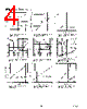
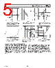
5 / 8 page  AD736 REV. C –5– Typical Characteristics– Figure 10. Error vs. RMS Input Voltage (Pin 2), Output Buffer Off- set Is Adjusted To Zero Figure 13. Pin 2 Input Bias Current vs. Supply Voltage CALCULATING SETTLING TIME USING FIGURE 14 The graph of Figure 14 may be used to closely approximate the time required for the AD736 to settle when its input level is re- duced in amplitude. The net time required for the rms converter to settle will be the difference between two times extracted from the graph – the initial time minus the final settling time. As an example, consider the following conditions: a 33 µF averaging capacitor, an initial rms input level of 100 mV and a final (re- duced) input level of 1 mV. From Figure 14, the initial settling time (where the 100 mV line intersects the 33 µF line) is around 80 ms. The settling time corresponding to the new or final input level of 1 mV is approximately 8 seconds. Therefore, the net time for the circuit to settle to its new value will be 8 seconds minus 80 ms which is 7.92 seconds. Note that, because of the smooth decay characteristic inherent with a capacitor/diode combina- tion, this is the total settling time to the final value (i.e., not the settling time to 1%, 0.1%, etc., of final value). Also, this graph provides the worst case settling time, since the AD736 will settle very quickly with increasing input levels. Figure 11. CAV vs. Frequency for Specified Averaging Error Figure 14. Settling Time vs. RMS Input Level for Various Values of CAV Figure 12. RMS Input Level vs. Frequency for Specified Averag- ing Error Figure 15. Pin 2 Input Bias Cur- rent vs. Temperature |
|
|
Ligação URL |
| ALLDATASHEET é útil para você? [ DONATE ] |
Sobre Alldatasheet | Publicidade | Contato conosco | Privacy Policy | Link para a ficha técnica | roca de Link | Lista de Fabricantes All Rights Reserved©Alldatasheet.com |
| Russian : Alldatasheetru.com | Korean : Alldatasheet.co.kr | Spanish : Alldatasheet.es | French : Alldatasheet.fr | Italian : Alldatasheetit.com Portuguese : Alldatasheetpt.com | Polish : Alldatasheet.pl | Vietnamese : Alldatasheet.vn Indian : Alldatasheet.in | Mexican : Alldatasheet.com.mx | British : Alldatasheet.co.uk | New Zealand : Alldatasheet.co.nz |
|
Family Site : ic2ic.com |
icmetro.com |
 Portuguese ▼
 English
 Chinese
 German
 Japanese
 Russian
 Korean
 Spanish
 French
 Italian
 Portuguese
 Polish
 Vietnamese
 Indian
 Mexican
 British
 New Zealand