|
Os motores de busca de Datasheet de Componentes eletrônicos |
|
|
Os motores de busca de Datasheet de Componentes eletrônicos |
|
SP4501 Folha de dados(PDF) 9 Page - Sipex Corporation |
|
|
|||||||||||||||||||||||||||||
SP4501 Folha de dados(HTML) 9 Page - Sipex Corporation |
|
|
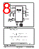
9 / 13 page  11-14-00 SP4501 EL Plus Piezo Driver © Copyright 2000 Sipex Corporation 9 PIN ASSIGNMENTS Pin 1 — ELEN — Electroluminescent Lamp Enable. When driven HIGH, this input pin enables the EL driver outputs. This pin has an internal pulldown resistor. Pin 2 — PZEN — Piezo Enable. When this input pin is driven HIGH, the piezo operates at a frequency f OSC/16. When this input pin is LOW, the clock signals applied to PZCK or PZCK will drive the internal piezo circuitry. This pin has an internal pulldown resistor. Pin 3 — R OSC — Oscillator Resistor. Connecting a resistor between this pin and V DD sets the frequency of the internal clock. Pin 4 — PZCK — Inverse Piezo Clock. When PZEN is LOW, the internal piezo circuit will operate at the frequency of the clock signal applied to this input pin. For the piezo driver to rest in the inactive mode, it is required that PZCK remains at logic HIGH. This pin has an internal pullup resistor. Pin 5 — PZCK — Piezo Clock. When PZEN is LOW, the internal piezo circuit will operate at the frequency of the clock signal applied to this input pin. For the piezo driver to rest in the inactive mode, it is required that PZCK remains at logic LOW. This pin has an internal pulldown resistor. Pin 6 — No connect. . Pin 7 — V SS — Power Supply Ground. Connect to the lowest circuit potential, typically ground Pin 8 — COIL — Coil. The inductor for the boost converter is connected from V BATT to this pin. Pin 9 — CAP — Integrator Capacitor. An integrator capacitor connected from this pin to ground filters out any coil switching spikes or ripple present in the output waveform to the EL lamp. Connecting a fast recovery diode from COIL to CAP increases the light output of the EL lamp. Pin 10 — PZ1 — Piezotransducer Output. Con- nect this pin to the piezotransducer. Pin 11 — PZ2 — Piezotransducer Output. Con- nect this pin to the piezotransducer. Pin 12 — EL1 — Electroluminescent Lamp Output. Connect this pin to the EL lamp. Pin 13 — EL2 — Electroluminescent Lamp Output. Connect this pin to the EL lamp. Pin 14 — V DD — Positive Power Supply. This pin should be bypassed with a 0.1 µF capaci- tor. |
|
|
Ligação URL |
| ALLDATASHEET é útil para você? [ DONATE ] |
Sobre Alldatasheet | Publicidade | Contato conosco | Privacy Policy | Link para a ficha técnica | roca de Link | Lista de Fabricantes All Rights Reserved©Alldatasheet.com |
| Russian : Alldatasheetru.com | Korean : Alldatasheet.co.kr | Spanish : Alldatasheet.es | French : Alldatasheet.fr | Italian : Alldatasheetit.com Portuguese : Alldatasheetpt.com | Polish : Alldatasheet.pl | Vietnamese : Alldatasheet.vn Indian : Alldatasheet.in | Mexican : Alldatasheet.com.mx | British : Alldatasheet.co.uk | New Zealand : Alldatasheet.co.nz |
|
Family Site : ic2ic.com |
icmetro.com |
 Portuguese ▼
 English
 Chinese
 German
 Japanese
 Russian
 Korean
 Spanish
 French
 Italian
 Portuguese
 Polish
 Vietnamese
 Indian
 Mexican
 British
 New Zealand