|
Os motores de busca de Datasheet de Componentes eletrônicos |
|
|
Os motores de busca de Datasheet de Componentes eletrônicos |
|
MCP6244 Folha de dados(PDF) 12 Page - Microchip Technology |
|
|
|||||||||||||||||||||||||||||
MCP6244 Folha de dados(HTML) 12 Page - Microchip Technology |
|
|
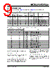
12 / 38 page  MCP6241/1R/1U/2/4 DS21882D-page 12 © 2008 Microchip Technology Inc. A significant amount of current can flow out of the inputs when the common mode voltage (VCM) is below ground (VSS); see Figure 2-19. Applications that are high impedance may need to limit the useable voltage range. 4.1.3 NORMAL OPERATION The input stage of the MCP6241/1R/1U/2/4 op amps use two differential CMOS input stages in parallel. One operates at low common mode input voltage (VCM), while the other operates at high VCM. WIth this topol- ogy, the device operates with VCM up to 0.3V above VDD and 0.3V below VSS. 4.2 Rail-to-Rail Output The output voltage range of the MCP6241/1R/1U/2/4 op amps is VDD –35mV (maximum) and VSS +35mV (minimum) when RL =10kΩ is connected to VDD/2 and VDD = 5.5V. Refer to Figure 2-14 for more information. 4.3 Capacitive Loads Driving large capacitive loads can cause stability problems for voltage-feedback op amps. As the load capacitance increases, the feedback loop’s phase margin decreases and the closed-loop bandwidth is reduced. This produces gain peaking in the frequency response, with overshoot and ringing in the step response. A unity-gain buffer (G = +1) is the most sensitive to capacitive loads, but all gains show the same general behavior. When driving large capacitive loads with these op amps (e.g., > 70 pF when G = +1), a small series resistor at the output (RISO in Figure 4-4) improves the feedback loop’s phase margin (stability) by making the output load resistive at higher frequencies. The bandwidth will be generally lower than the bandwidth with no capacitive load. FIGURE 4-4: Output Resistor, RISO stabilizes large capacitive loads. Figure 4-5 gives recommended RISO values for different capacitive loads and gains. The x-axis is the normalized load capacitance (CL/GN), where GN is the circuit’s noise gain. For non-inverting gains, GN and the signal gain are equal. For inverting gains, GN is 1 + |Signal Gain| (e.g., –1 V/V gives GN = +2 V/V). FIGURE 4-5: Recommended RISO Values for Capacitive Loads. After selecting RISO for your circuit, double-check the resulting frequency response peaking and step response overshoot. Evaluation on the bench and simulations with the MCP6241/1R/1U/2/4 SPICE macro model are very helpful. Modify RISO’s value until the response is reasonable. 4.4 Supply Bypass With this op amp, the power supply pin (VDD for single-supply) should have a local bypass capacitor (i.e., 0.01 µF to 0.1 µF) within 2 mm for good high- frequency performance. It can use a bulk capacitor (i.e., 1 µF or larger) within 100 mm to provide large, slow currents. This bulk capacitor can be shared with other nearby analog parts. 4.5 Unused Op Amps An unused op amp in a quad package (MCP6244) should be configured as shown in Figure 4-6. Both circuits prevent the output from toggling and causing crosstalk. Circuit A can use any reference voltage between the supplies, provides a buffered DC voltage, and minimizes the supply current draw of the unused op amp. Circuit B minimizes the number of components, but may draw a little more supply current for the unused op amp. FIGURE 4-6: Unused Op Amps. VIN RISO VOUT MCP624X CL – + 1.E+02 1.E+03 1.E+04 1.E+01 1.E+02 1.E+03 1.E+04 Normalized Load Capacitance; CL/GN (F) 10p 100p 1n 10n 10k 1k 100 GN = +1 V/V GN ≥ +2 V/V VDD VDD ¼ MCP6244 (A) ¼ MCP6244 (B) R1 R2 VDD VREF V REF V DD R 2 R 1 R 2 + ------------------ ⋅ = |
|
Ligação URL |
| ALLDATASHEET é útil para você? [ DONATE ] |
Sobre Alldatasheet | Publicidade | Contato conosco | Privacy Policy | Link para a ficha técnica | roca de Link | Lista de Fabricantes All Rights Reserved©Alldatasheet.com |
| Russian : Alldatasheetru.com | Korean : Alldatasheet.co.kr | Spanish : Alldatasheet.es | French : Alldatasheet.fr | Italian : Alldatasheetit.com Portuguese : Alldatasheetpt.com | Polish : Alldatasheet.pl | Vietnamese : Alldatasheet.vn Indian : Alldatasheet.in | Mexican : Alldatasheet.com.mx | British : Alldatasheet.co.uk | New Zealand : Alldatasheet.co.nz |
|
Family Site : ic2ic.com |
icmetro.com |
 Portuguese ▼
 English
 Chinese
 German
 Japanese
 Russian
 Korean
 Spanish
 French
 Italian
 Portuguese
 Polish
 Vietnamese
 Indian
 Mexican
 British
 New Zealand