|
Os motores de busca de Datasheet de Componentes eletrônicos |
|
|
Os motores de busca de Datasheet de Componentes eletrônicos |
|
MCP6001 Folha de dados(PDF) 10 Page - Microchip Technology |
|
|
|||||||||||||||||||||||||||||
MCP6001 Folha de dados(HTML) 10 Page - Microchip Technology |
|
|
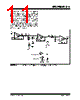
10 / 28 page  MCP6001/2/4 DS21733F-page 10 © 2005 Microchip Technology Inc. 4.6 Application Circuits 4.6.1 UNITY-GAIN BUFFER The rail-to-rail input and output capability of the MCP6001/2/4 op amp is ideal for unity-gain buffer applications. The low quiescent current and wide bandwidth makes the device suitable for a buffer configuration in an instrumentation amplifier circuit, as shown in Figure 4-6. FIGURE 4-6: Instrumentation Amplifier with Unity-Gain Buffer Inputs. 4.6.2 ACTIVE LOW-PASS FILTER The MCP6001/2/4 op amp’s low input bias current makes it possible for the designer to use larger resis- tors and smaller capacitors for active low-pass filter applications. However, as the resistance increases, the noise generated also increases. Parasitic capacitances and the large value resistors could also modify the fre- quency response. These trade-offs need to be considered when selecting circuit elements. Usually, the op amp bandwidth is 100X the filter cutoff frequency (or higher) for good performance. It is possi- ble to have the op amp bandwidth 10X higher than the cutoff frequency, thus having a design that is more sensitive to component tolerances. Figure 4-7 shows a second-order Butterworth filter with 100 kHz cutoff frequency and a gain of +1 V/V; the op amp bandwidth is only 10X higher than the cutoff frequency. The component values were selected using Microchip’s FilterLab® software. FIGURE 4-7: Active Second-Order Low- Pass Filter. 4.6.3 PEAK DETECTOR The MCP6001/2/4 op amp has a high input impedance, rail-to-rail input/output and low input bias current, which makes this device suitable for peak detector applica- tions. Figure 4-8 shows a peak detector circuit with clear and sample switches. The peak-detection cycle uses a clock (CLK), as shown in Figure 4-8. At the rising edge of CLK, Sample Switch closes to begin sampling. The peak voltage stored on C1 is sam- pled to C2 for a sample time defined by tSAMP. At the end of the sample time (falling edge of Sample Signal), Clear Signal goes high and closes the Clear Switch. When the Clear Switch closes, C1 discharges through R1 for a time defined by tCLEAR. At the end of the clear time (falling edge of Clear Signal), op amp A begins to store the peak value of VIN on C1 for a time defined by tDETECT. In order to define tSAMP and tCLEAR, it is necessary to determine the capacitor charging and discharging period. The capacitor charging time is limited by the amplifier source current, while the discharging time ( τ) is defined using R1 ( τ = R 1C1). tDETECT is the time that the input signal is sampled on C1 and is dependent on the input voltage change frequency. The op amp output current limit, and the size of the storage capacitors (both C1 and C2), could create slew- ing limitations as the input voltage (VIN) increases. Current through a capacitor is dependent on the size of the capacitor and the rate of voltage change. From this relationship, the rate of voltage change or the slew rate can be determined. For example, with an op amp short- circuit current of ISC = 25 mA and a load capacitor of C1 = 0.1 µF, then: EQUATION 4-1: VIN1 R2 MCP6002 VIN2 R2 MCP6002 VREF MCP6001 VOUT R1 R1 – + – + – + 1/2 1/2 V OUT V IN2 V IN1 – () R 1 R 2 ------ • V REF + = R1 = 20 kΩ R2 = 10 kΩ 14.3 k Ω MCP6002 VOUT 53.6 k Ω 100 pF VIN 33 pF + – dV C1 dt ------------- I SC C 1 -------- = 25mA 0.1 μF --------------- = dV C1 dt ------------- 250mV μs ⁄ = I SC C 1 dV C1 dt ------------- = |
|
Ligação URL |
| ALLDATASHEET é útil para você? [ DONATE ] |
Sobre Alldatasheet | Publicidade | Contato conosco | Privacy Policy | Link para a ficha técnica | roca de Link | Lista de Fabricantes All Rights Reserved©Alldatasheet.com |
| Russian : Alldatasheetru.com | Korean : Alldatasheet.co.kr | Spanish : Alldatasheet.es | French : Alldatasheet.fr | Italian : Alldatasheetit.com Portuguese : Alldatasheetpt.com | Polish : Alldatasheet.pl | Vietnamese : Alldatasheet.vn Indian : Alldatasheet.in | Mexican : Alldatasheet.com.mx | British : Alldatasheet.co.uk | New Zealand : Alldatasheet.co.nz |
|
Family Site : ic2ic.com |
icmetro.com |
 Portuguese ▼
 English
 Chinese
 German
 Japanese
 Russian
 Korean
 Spanish
 French
 Italian
 Portuguese
 Polish
 Vietnamese
 Indian
 Mexican
 British
 New Zealand