|
Os motores de busca de Datasheet de Componentes eletrônicos |
|
|
Os motores de busca de Datasheet de Componentes eletrônicos |
|
C0805Y393DGGACTU Folha de dados(PDF) 23 Page - Kemet Corporation |
|
|
|||||||||||||||||||||||||||||
C0805Y393DGGACTU Folha de dados(HTML) 23 Page - Kemet Corporation |
|
|
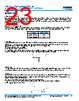
23 / 24 page  23 © KEMET Electronics Corporation • KEMET Tower • One East Broward Boulevard C1126_C0G_HV_FF-CAP_SMD • 2/16/2023 Fort Lauderdale, FL 33301 USA • 954-766-2800 • www.kemet.com Surface Mount Multilayer Ceramic Chip Capacitors (SMD MLCCs) Floating Electrode (FF-CAP), High Voltage with Flexible Termination C0G Dielectric, 500 – 3,000 VDC (Commercial & Automotive Grade) Application Guide Solder Fluxes and Cleaning The use of water-soluble fluxes provides advantages of excellent solderability due to high activation. However, these fluxes contain organic acids that can induce arcing under high DC or AC voltages. Notable problem areas are underneath the MLCC where flux can be trapped between the ceramic material and PCB. It is therefore critical that PCBs are properly cleaned to remove all flux residue to maintain reliability. Coating for High Voltage MLCCs For MLCC ratings ≥1500V, it is recommended to apply a conformal coating to MLCC to prevent surface arcing. To reduce possibility of inducing cracks in the MLCC, select a coating with thermal expansions close to that of the MLCC. Dielectric CTE (ppm/°C) Class II BaTiO 3 10.7 Class I CaZrO 3 9.8 Slits in PCB It is recommended to apply a slit in the PCB under the MLCC to improve washing of flux residue that may get trapped underneath. In some cases, it is not possible to slit entirely through the PCB due to underlying metal planes. It is also acceptable to apply a recessed slit under the MLCC which will also promote cleaning. • Recommended for case sizes ≥1206 • The width (w) of the slit should be 1mm • Length of the slit should be as short as possible to prevent damaging the MLCC due to mechanical stress of the PCB. • Slits also reduce the risk of solder balls under MLCC which decreased the creepage distance. Solder Resist If a slit cannot be applied as above, it is recommended to not use solder resist directly under the MLCC. The use of solder resist material reduces the distance between MLCC ceramic material and PCB thus making it difficult to clean. Solder Balls Improper reflow techniques and/or improper washing can induce solder balls under or adjacent to the MLCC. Solder balls reduce the creepage distance between the MLCC terminations and increase the risk of arcing or damage to the ceramic material. To reduce the risk of solder balls: • Follow KEMET’s solder recommendations as outlined in the datasheet. • If performing a cleaning procedure, properly clean the PCB per KEMET’s cleaning recommendations. • Add slit to the PCB as shown above. |
|
|
Ligação URL |
| ALLDATASHEET é útil para você? [ DONATE ] |
Sobre Alldatasheet | Publicidade | Contato conosco | Privacy Policy | Link para a ficha técnica | roca de Link | Lista de Fabricantes All Rights Reserved©Alldatasheet.com |
| Russian : Alldatasheetru.com | Korean : Alldatasheet.co.kr | Spanish : Alldatasheet.es | French : Alldatasheet.fr | Italian : Alldatasheetit.com Portuguese : Alldatasheetpt.com | Polish : Alldatasheet.pl | Vietnamese : Alldatasheet.vn Indian : Alldatasheet.in | Mexican : Alldatasheet.com.mx | British : Alldatasheet.co.uk | New Zealand : Alldatasheet.co.nz |
|
Family Site : ic2ic.com |
icmetro.com |
 Portuguese ▼
 English
 Chinese
 German
 Japanese
 Russian
 Korean
 Spanish
 French
 Italian
 Portuguese
 Polish
 Vietnamese
 Indian
 Mexican
 British
 New Zealand