|
Os motores de busca de Datasheet de Componentes eletrônicos |
|
|
Os motores de busca de Datasheet de Componentes eletrônicos |
|
IT1 Folha de dados(PDF) 9 Page - Hirose Electric |
|
|
|||||||||||||||||||||||||||||
IT1 Folha de dados(HTML) 9 Page - Hirose Electric |
|
|
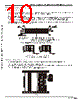
9 / 17 page  A302 IT1 Series ●High Speed, Matched-Impedance, Parallel Board-to-board Connector System BConnector Handling Precautions 1. System components ■Receptacles ¡Contacts ¡Row A and row B contacts are arranged alternately starting with No.1 in row B. Placement on board is polarized. ¡Metal Fittings ¡Permanently inserted to provide lock with the Transmission Module and additional solder areas with the PCB. ¡Insulator body. ¡Injection molded single unit provides protection and correct self-alignment of all components. ■Transmission Module Assembly ¡Each Module has stationary side and a mating/un-mating side. ¡When mounting multiple connectors, please keep uniform orientation of the stationary side. ¡Transmission printed circuit boards used in the module are based on JIS standards and quality standards applicable to memory modules. Guide frame Transmission boards. Mating/ un- mating side Stationary side Mating/ un-mating side (Short) Stationary side (Longer) Even numbered row: A contacts Odd numbered row: B contacts Insulator body Metal fittings Receptacles Transmission module assembly ■Extraction Tool ¡Used to release the transmission module from the stationary receptacle. Extraction Tool (2 required) Fully Connected Condition The interconnection package consists of 3 main sub-assemblies: Two receptacles and the Transmission Module. The transmission module, held securely by the guide frame has a mating/un-mating side and a stationary side. Once the stationary side is inserted in the receptacle, it can not be removed without the use of extraction tool. The mating/un-mating side allows repeated re-insertion of the receptacle on this side only. |
|
|
Ligação URL |
| ALLDATASHEET é útil para você? [ DONATE ] |
Sobre Alldatasheet | Publicidade | Contato conosco | Privacy Policy | Link para a ficha técnica | roca de Link | Lista de Fabricantes All Rights Reserved©Alldatasheet.com |
| Russian : Alldatasheetru.com | Korean : Alldatasheet.co.kr | Spanish : Alldatasheet.es | French : Alldatasheet.fr | Italian : Alldatasheetit.com Portuguese : Alldatasheetpt.com | Polish : Alldatasheet.pl | Vietnamese : Alldatasheet.vn Indian : Alldatasheet.in | Mexican : Alldatasheet.com.mx | British : Alldatasheet.co.uk | New Zealand : Alldatasheet.co.nz |
|
Family Site : ic2ic.com |
icmetro.com |
 Portuguese ▼
 English
 Chinese
 German
 Japanese
 Russian
 Korean
 Spanish
 French
 Italian
 Portuguese
 Polish
 Vietnamese
 Indian
 Mexican
 British
 New Zealand