 |
Os motores de busca de Datasheet de Componentes eletrônicos |
|
|
Os motores de busca de Datasheet de Componentes eletrônicos |
|
The question interval is too short.
Please try again in a few seconds.

Hello, Please ask a question about RFDA2015SR Datasheet
# Example questions:
➢ The bill of materials lists multiple capacitor values. what is the highest capacitance value listed, and what is its voltage rating?
➢ What is the primary function of pin 23 (d0)?
➢ What are the dimensions of the laminate module?
| Part No. | RFDA2015SR |
| Manufacturer | RFMD |
| Size | 1Mb |
| Pages | 10 pages |
| Description | DIGITAL CONTROLLED VARIABLE GAIN AMPLIFIER |


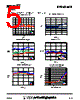
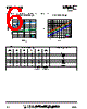


This document is a datasheet for the RFDA2015, a wideband, high-linearity attenuator integrated circuit (IC). Here's a breakdown of its contents:
Key Features & Function:
️· Wideband Attenuation: Designed for applications requiring variable attenuation across a broad frequency range (likely around 1.8-2.2 GHz, based on the bill of materials and schematic).
️· Digital Control: Uses a digital interface (6 control lines: D0-D5) to set the attenuation level. The data sheet details the step size for each bit (16dB, 8dB, 4dB, 2dB, 1dB, 0.5dB).
️· High Linearity: The datasheet highlights the device's ability to maintain signal integrity, which is important for applications needing low distortion.
Content Breakdown:
1. Performance Graphs: The initial pages show performance data:
- Attenuation vs. Frequency at different digital control settings.
- Input Return Loss and Output Return Loss as a function of frequency
- Isolation and Third-Order Intercept Point (TOI) which are related to the IC’s performance.
2. Absolute Maximum Ratings: These specify the limits that the IC must not exceed to prevent damage (voltage, current, power dissipation, operating temperature).
3. Electrical Characteristics: Detailed performance specifications under specified test conditions. These specs define things like input power level, output power level, attenuation range, and DC operating parameters.
4. Application Circuit:
- Evaluation Schematic: A complete circuit diagram showing how to connect the RFDA2015 in a test setup.
- Bill of Materials (BOM): Lists all the components used in the evaluation circuit, including manufacturers and part numbers.
5. Package & Pinout: Describes the physical package dimensions and the function of each pin on the IC.
6. Package Drawing: Shows the physical dimensions of the RFDA2015 package
7. Trace Code: Information on how the product is traced for manufacturing purposes.
Target Applications:
Based on the features and specifications, the RFDA2015 is likely intended for use in:
️· Wireless Infrastructure (Base Stations, Repeaters)
️· Wireless Communication (Cellular, WiMAX)
️· Test and Measurement Equipment
️· Software-Defined Radio (SDR)
️· Any application requiring precise, digitally controlled attenuation over a wide frequency range.
In essence, this datasheet is a comprehensive guide for engineers designing and implementing the RFDA2015 into their systems.
Key Features & Function:
️· Wideband Attenuation: Designed for applications requiring variable attenuation across a broad frequency range (likely around 1.8-2.2 GHz, based on the bill of materials and schematic).
️· Digital Control: Uses a digital interface (6 control lines: D0-D5) to set the attenuation level. The data sheet details the step size for each bit (16dB, 8dB, 4dB, 2dB, 1dB, 0.5dB).
️· High Linearity: The datasheet highlights the device's ability to maintain signal integrity, which is important for applications needing low distortion.
Content Breakdown:
1. Performance Graphs: The initial pages show performance data:
- Attenuation vs. Frequency at different digital control settings.
- Input Return Loss and Output Return Loss as a function of frequency
- Isolation and Third-Order Intercept Point (TOI) which are related to the IC’s performance.
2. Absolute Maximum Ratings: These specify the limits that the IC must not exceed to prevent damage (voltage, current, power dissipation, operating temperature).
3. Electrical Characteristics: Detailed performance specifications under specified test conditions. These specs define things like input power level, output power level, attenuation range, and DC operating parameters.
4. Application Circuit:
- Evaluation Schematic: A complete circuit diagram showing how to connect the RFDA2015 in a test setup.
- Bill of Materials (BOM): Lists all the components used in the evaluation circuit, including manufacturers and part numbers.
5. Package & Pinout: Describes the physical package dimensions and the function of each pin on the IC.
6. Package Drawing: Shows the physical dimensions of the RFDA2015 package
7. Trace Code: Information on how the product is traced for manufacturing purposes.
Target Applications:
Based on the features and specifications, the RFDA2015 is likely intended for use in:
️· Wireless Infrastructure (Base Stations, Repeaters)
️· Wireless Communication (Cellular, WiMAX)
️· Test and Measurement Equipment
️· Software-Defined Radio (SDR)
️· Any application requiring precise, digitally controlled attenuation over a wide frequency range.
In essence, this datasheet is a comprehensive guide for engineers designing and implementing the RFDA2015 into their systems.
| Part No. | RFDA2015SR |
| Manufacturer | RFMD |
| Size | 1Mb |
| Pages | 10 pages |
| Description | DIGITAL CONTROLLED VARIABLE GAIN AMPLIFIER |
| ALLDATASHEET é útil para você? [ DONATE ] |
Sobre Alldatasheet | Publicidade | Contato conosco | Privacy Policy | Link para a ficha técnica | roca de Link | Lista de Fabricantes All Rights Reserved©Alldatasheet.com |
| Russian : Alldatasheetru.com | Korean : Alldatasheet.co.kr | Spanish : Alldatasheet.es | French : Alldatasheet.fr | Italian : Alldatasheetit.com Portuguese : Alldatasheetpt.com | Polish : Alldatasheet.pl | Vietnamese : Alldatasheet.vn Indian : Alldatasheet.in | Mexican : Alldatasheet.com.mx | British : Alldatasheet.co.uk | New Zealand : Alldatasheet.co.nz |
|
Family Site : ic2ic.com |
icmetro.com |
 Portuguese ▼
  English
 Chinese
 German
 Japanese
 Russian
 Korean
 Spanish
 French
 Italian
 Polish
 Vietnamese
 Indian
 Mexican
 British
 New Zealand