 |
Os motores de busca de Datasheet de Componentes eletrônicos |
|
|
Os motores de busca de Datasheet de Componentes eletrônicos |
|
The question interval is too short.
Please try again in a few seconds.

Hello, Please ask a question about PIC16C712 Datasheet
# Example questions:
➢ What does the 'adon' bit in the adcon0 register control?
➢ What is the function of the pclath register?
➢ What values are reserved bits represented as?
| Part No. | PIC16C712 |
| Manufacturer | MICROCHIP |
| Size | 1Mb |
| Pages | 106 pages |
| Description | 8-Bit CMOS Microcontrollers with A/D Converter and Capture/Compare/PWM |




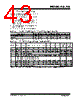






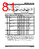


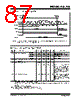





1. Overview: Special Function Registers (SFRs)
️· The document describes the Special Function Registers (SFRs) that control various peripherals and functions within the PIC16C712/716 microcontroller.
️· SFRs are critical for interacting with the microcontroller’s hardware.
️· The table provides the address, a brief description of each register, and its initial value after a reset.
2. Addressing and Bank Considerations
️· Some SFRs can be addressed from either bank of memory (Bank 0 or Bank 1). These are specifically noted.
️· The *Program Counter High* register (PCLATH) is a special case; it's a holding register, not directly accessible.
️· The *Instruction Register Pointer* and *RP1* bits are reserved and should be kept clear (set to 0).
3. Key Registers and their Functions (Highlights - not exhaustive)
️· PORTA/PORTB: Data latches and pins for Port A and Port B. After a reset, these are configured as inputs.
️· DATACC: CCP Data Latch. Associated with the CCP module.
️· PCLATH: Holds the upper 5 bits of the Program Counter.
️· INTCON: Contains flags and controls for interrupts (e.g., GIE – global interrupt enable, T0IF – Timer0 interrupt flag).
️· PIR1: Peripheral Interrupt Register 1. Contains flags for peripheral interrupts (CCP1IF, TMR2IF, TMR1IF).
️· T1CON: Timer 1 control register – sets prescaler, clock source, and mode.
️· T2CON: Timer 2 control register.
️· CCP1CON: CCP1 control register - controls CCP module functionality (PWM, capture, compare).
️· ADRES: A/D result register - holds the result of an analog-to-digital conversion.
️· ADCON0: A/D control register 0 - configures the A/D converter.
4. Notes & Caveats
️· Unimplemented bits should be read as '0'.
️· 'x' in the table indicates an unknown value, and 'u' represents an unchanged value (meaning the bit maintains its value after a reset or other event).
️· The '–' characters represent unimplemented locations that should be read as '0'.
In essence, this document is a reference guide to the PIC16C712/716 microcontroller's internal registers, essential for understanding how to control its peripherals and functionality. It's a technical document intended for programmers and hardware engineers working with these microcontrollers. For complete understanding, refer to the full datasheet.
1. Overview: Special Function Registers (SFRs)
️· The document describes the Special Function Registers (SFRs) that control various peripherals and functions within the PIC16C712/716 microcontroller.
️· SFRs are critical for interacting with the microcontroller’s hardware.
️· The table provides the address, a brief description of each register, and its initial value after a reset.
2. Addressing and Bank Considerations
️· Some SFRs can be addressed from either bank of memory (Bank 0 or Bank 1). These are specifically noted.
️· The *Program Counter High* register (PCLATH) is a special case; it's a holding register, not directly accessible.
️· The *Instruction Register Pointer* and *RP1* bits are reserved and should be kept clear (set to 0).
3. Key Registers and their Functions (Highlights - not exhaustive)
️· PORTA/PORTB: Data latches and pins for Port A and Port B. After a reset, these are configured as inputs.
️· DATACC: CCP Data Latch. Associated with the CCP module.
️· PCLATH: Holds the upper 5 bits of the Program Counter.
️· INTCON: Contains flags and controls for interrupts (e.g., GIE – global interrupt enable, T0IF – Timer0 interrupt flag).
️· PIR1: Peripheral Interrupt Register 1. Contains flags for peripheral interrupts (CCP1IF, TMR2IF, TMR1IF).
️· T1CON: Timer 1 control register – sets prescaler, clock source, and mode.
️· T2CON: Timer 2 control register.
️· CCP1CON: CCP1 control register - controls CCP module functionality (PWM, capture, compare).
️· ADRES: A/D result register - holds the result of an analog-to-digital conversion.
️· ADCON0: A/D control register 0 - configures the A/D converter.
4. Notes & Caveats
️· Unimplemented bits should be read as '0'.
️· 'x' in the table indicates an unknown value, and 'u' represents an unchanged value (meaning the bit maintains its value after a reset or other event).
️· The '–' characters represent unimplemented locations that should be read as '0'.
In essence, this document is a reference guide to the PIC16C712/716 microcontroller's internal registers, essential for understanding how to control its peripherals and functionality. It's a technical document intended for programmers and hardware engineers working with these microcontrollers. For complete understanding, refer to the full datasheet.
| Part No. | PIC16C712 |
| Manufacturer | MICROCHIP |
| Size | 1Mb |
| Pages | 106 pages |
| Description | 8-Bit CMOS Microcontrollers with A/D Converter and Capture/Compare/PWM |
| ALLDATASHEET é útil para você? [ DONATE ] |
Sobre Alldatasheet | Publicidade | Contato conosco | Privacy Policy | Link para a ficha técnica | roca de Link | Lista de Fabricantes All Rights Reserved©Alldatasheet.com |
| Russian : Alldatasheetru.com | Korean : Alldatasheet.co.kr | Spanish : Alldatasheet.es | French : Alldatasheet.fr | Italian : Alldatasheetit.com Portuguese : Alldatasheetpt.com | Polish : Alldatasheet.pl | Vietnamese : Alldatasheet.vn Indian : Alldatasheet.in | Mexican : Alldatasheet.com.mx | British : Alldatasheet.co.uk | New Zealand : Alldatasheet.co.nz |
|
Family Site : ic2ic.com |
icmetro.com |
 Portuguese ▼
  English
 Chinese
 German
 Japanese
 Russian
 Korean
 Spanish
 French
 Italian
 Polish
 Vietnamese
 Indian
 Mexican
 British
 New Zealand