 |
Os motores de busca de Datasheet de Componentes eletrônicos |
|
|
Os motores de busca de Datasheet de Componentes eletrônicos |
|
The question interval is too short.
Please try again in a few seconds.

Hello, Please ask a question about IT1 Datasheet
# Example questions:
➢ What are they, and how many receptacles does each typically hold for the 168-contact version?
➢ What is the primary function of the 'it1-picker(1)' tool?
➢ What is the importance of verifying the packaging type and pick-and-place areas when using automatic placement equipment?
| Part No. | IT1 |
| Manufacturer | HIROSE |
| Size | 538 Kbytes |
| Pages | 17 pages |
| Description | High Speed, Matched-Impedance, Parallel Board-to-board Connector |


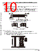


Document Title: IT1 Series – High-Speed Parallel Board-to-Board Connectors (Te Connectivity)
Overall Purpose: This document is a comprehensive guide for engineers and designers using Te Connectivity's IT1 series of high-speed parallel board-to-board connectors. It covers specifications, handling, placement, and design considerations.
1. Connector Types and Features
️· Available Configurations:
- 168-contact receptacles
- 252-contact receptacles
️· Key Components & Design:
- Receptacles: Contain contacts, metal fittings (for lock and solder), and an insulator body. Row A and Row B contacts are arranged alternately.
- Transmission Module Assembly: Has a stationary side and a mating/un-mating side.
- Extraction Tool: Required to remove the transmission module from the receptacle.
️· Fully Connected Condition: Odd-numbered row has B contacts.
2. Handling & Placement Considerations
️· Connector Handling Precautions:
- System Components: Describes components (receptacles, transmission module assembly, extraction tool).
- Orientation: Maintain uniform orientation of stationary sides when placing multiple connectors.
- Extraction Tool: Used to release the transmission module from the stationary receptacle.
️· Design Guidelines:
- Solder Land Pattern: Accurate hole diameters are crucial. Avoid conductive traces under the receptacle assemblies. Refer to separate drawings for dimensions.
- Board-to-Board Spacers: Important for maintaining connector height tolerance and ensuring proper mating. The design depends on the board-to-board distance (example: 19mm).
️· Packaging:
- Semi-hard tray: 40 (168 contacts) or 30 (252 contacts) per tray
- Hard tray: 24 (168 contacts) or 16 (252 contacts) per tray
️· Automatic Placement:
- Refer to "Vacuum Pick-up Tape Specification"
- Refer to diagrams for pick-and-place areas.
️· Manual Placement:
- Orientation posts prevent incorrect placement.
- Ensure correct contact alignment with solder pads.
3. Design Details & Specifications
️· Locating Post Hole Diameter:
- Automatic Placement: 1.7 mm
- Manual Placement: 1.6 mm
️· Board-to-Board Distance: Example of 19mm provided for spacer height guidelines.
️· Recommended Reflow Conditions: (Not detailed in the excerpt, refer to separate documents).
️· Connector Heights & Tolerances: (Refer to Fig. 4)
4. Key Drawings & Diagrams (referenced but not fully presented in the provided text)
️· Fig. 1: IT1-168S-SV Recommended Solder Land Pattern
️· Fig. 2: Cross section of IT1 receptacle
️· Fig. 3: Board-to-Board Spacer heights (19mm example)
️· Fig. 4: Manual placement guidelines (Correct vs. Incorrect)
️· Vacuum Pick-up Tape Specification Diagram
️· Pick-and-Place Areas Diagram
Important Notes for Engineers/Designers:
️· Refer to Separate Drawings: Many crucial details (solder land patterns, connection diagrams, reflow conditions) are found in separate drawings referenced in the document. Obtain and review these drawings for complete design information.
️· Locating Post Accuracy: The position accuracy of the hole centers should be within [+] -0.03 of contact number 84.
️· Manual Placement Risks: Be especially careful with manual placement to prevent misalignment.
️· Spacer Height is Critical: Proper spacer height is crucial for connector function and reliable board-to-board connection.
️· Vacuum Pick-up: If automated placement is used, pay close attention to the Vacuum Pick-up Tape Specification.
Document Title: IT1 Series – High-Speed Parallel Board-to-Board Connectors (Te Connectivity)
Overall Purpose: This document is a comprehensive guide for engineers and designers using Te Connectivity's IT1 series of high-speed parallel board-to-board connectors. It covers specifications, handling, placement, and design considerations.
1. Connector Types and Features
️· Available Configurations:
- 168-contact receptacles
- 252-contact receptacles
️· Key Components & Design:
- Receptacles: Contain contacts, metal fittings (for lock and solder), and an insulator body. Row A and Row B contacts are arranged alternately.
- Transmission Module Assembly: Has a stationary side and a mating/un-mating side.
- Extraction Tool: Required to remove the transmission module from the receptacle.
️· Fully Connected Condition: Odd-numbered row has B contacts.
2. Handling & Placement Considerations
️· Connector Handling Precautions:
- System Components: Describes components (receptacles, transmission module assembly, extraction tool).
- Orientation: Maintain uniform orientation of stationary sides when placing multiple connectors.
- Extraction Tool: Used to release the transmission module from the stationary receptacle.
️· Design Guidelines:
- Solder Land Pattern: Accurate hole diameters are crucial. Avoid conductive traces under the receptacle assemblies. Refer to separate drawings for dimensions.
- Board-to-Board Spacers: Important for maintaining connector height tolerance and ensuring proper mating. The design depends on the board-to-board distance (example: 19mm).
️· Packaging:
- Semi-hard tray: 40 (168 contacts) or 30 (252 contacts) per tray
- Hard tray: 24 (168 contacts) or 16 (252 contacts) per tray
️· Automatic Placement:
- Refer to "Vacuum Pick-up Tape Specification"
- Refer to diagrams for pick-and-place areas.
️· Manual Placement:
- Orientation posts prevent incorrect placement.
- Ensure correct contact alignment with solder pads.
3. Design Details & Specifications
️· Locating Post Hole Diameter:
- Automatic Placement: 1.7 mm
- Manual Placement: 1.6 mm
️· Board-to-Board Distance: Example of 19mm provided for spacer height guidelines.
️· Recommended Reflow Conditions: (Not detailed in the excerpt, refer to separate documents).
️· Connector Heights & Tolerances: (Refer to Fig. 4)
4. Key Drawings & Diagrams (referenced but not fully presented in the provided text)
️· Fig. 1: IT1-168S-SV Recommended Solder Land Pattern
️· Fig. 2: Cross section of IT1 receptacle
️· Fig. 3: Board-to-Board Spacer heights (19mm example)
️· Fig. 4: Manual placement guidelines (Correct vs. Incorrect)
️· Vacuum Pick-up Tape Specification Diagram
️· Pick-and-Place Areas Diagram
Important Notes for Engineers/Designers:
️· Refer to Separate Drawings: Many crucial details (solder land patterns, connection diagrams, reflow conditions) are found in separate drawings referenced in the document. Obtain and review these drawings for complete design information.
️· Locating Post Accuracy: The position accuracy of the hole centers should be within [+] -0.03 of contact number 84.
️· Manual Placement Risks: Be especially careful with manual placement to prevent misalignment.
️· Spacer Height is Critical: Proper spacer height is crucial for connector function and reliable board-to-board connection.
️· Vacuum Pick-up: If automated placement is used, pay close attention to the Vacuum Pick-up Tape Specification.
| Part No. | IT1 |
| Manufacturer | HIROSE |
| Size | 538 Kbytes |
| Pages | 17 pages |
| Description | High Speed, Matched-Impedance, Parallel Board-to-board Connector |
| ALLDATASHEET é útil para você? [ DONATE ] |
Sobre Alldatasheet | Publicidade | Contato conosco | Privacy Policy | Link para a ficha técnica | roca de Link | Lista de Fabricantes All Rights Reserved©Alldatasheet.com |
| Russian : Alldatasheetru.com | Korean : Alldatasheet.co.kr | Spanish : Alldatasheet.es | French : Alldatasheet.fr | Italian : Alldatasheetit.com Portuguese : Alldatasheetpt.com | Polish : Alldatasheet.pl | Vietnamese : Alldatasheet.vn Indian : Alldatasheet.in | Mexican : Alldatasheet.com.mx | British : Alldatasheet.co.uk | New Zealand : Alldatasheet.co.nz |
|
Family Site : ic2ic.com |
icmetro.com |
 Portuguese ▼
  English
 Chinese
 German
 Japanese
 Russian
 Korean
 Spanish
 French
 Italian
 Polish
 Vietnamese
 Indian
 Mexican
 British
 New Zealand