 |
Os motores de busca de Datasheet de Componentes eletrônicos |
|
|
Os motores de busca de Datasheet de Componentes eletrônicos |
|
The question interval is too short.
Please try again in a few seconds.

Hello, Please ask a question about HMC361 Datasheet
# Example questions:
➢ What are the absolute maximum ratings for rf input and vcc?
➢ Describe the function of the pwr sel pin and how it affects the output power of the hmc36
➢ What is the recommended wire diameter and bonding method for wire bonding to the hmc361 die?
| Part No. | HMC361 |
| Manufacturer | MICROSS |
| Size | 836 Kbytes |
| Pages | 9 pages |
| Description | Wide Bandwidth |



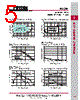
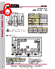


1. Device Overview:
️· What it is: A GaAs Heterojunction Bipolar Transistor (HBT) divide-by-two frequency multiplier MMIC (Monolithic Microwave Integrated Circuit).
️· Function: Takes an input signal and generates a frequency that is twice the input frequency.
️· Applications: Wireless communications, test equipment, and various RF systems.
2. Key Features & Specifications:
️· Input Frequency Range: Not explicitly stated but likely suitable for a wide range of RF frequencies.
️· Output Frequency: Double the input frequency.
️· Supply Voltage: 5V (with tolerance of ±0.25V)
️· Power Down: Can be powered down with a dedicated pin (PWR DWN).
️· Disable: Input buffer amplifier can be disabled via a control pin (DISABLE).
️· High/Low Power Modes: Selectable via the PWR SEL pin.
️· Differential Input/Output: Designed for both differential and single-ended operation.
️· Small Size: Die size is small (dimensions provided in the Outline Drawing section).
3. Absolute Maximum Ratings:
️· Vcc (Supply Voltage): +5.5V
️· VLogic (Logic Voltage): Within a specified range relative to Vcc.
️· Junction Temperature (Tj): 135 °C. Critical to avoid overheating.
️· Continuous Power Dissipation: Limited to avoid device failure. Derates as temperature increases.
️· Operating & Storage Temperature Range: Specified ranges to ensure reliable operation.
4. Electrical Characteristics:
️· Supply Current (Icc): Dependent on the supply voltage (Vcc).
️· Truth Table: Describes the functions of control pins (DISABLE, PWR DWN, PWR SEL).
5. Physical Characteristics & Mounting:
️· Die Size & Pad Layout: Detailed dimensions of the chip and the arrangement of bonding pads.
️· Back Metallization: Gold
️· Mounting:
- Epoxy die attach is recommended.
- Bonding pads are specified.
️· Wire Bonding: Specifies wire diameter, thermosonic parameters, and bond length limitations.
6. Handling Precautions:
️· Cleanliness: Requires a clean environment.
️· ESD Sensitivity: Requires static discharge precautions.
️· Transients: Control transient voltages.
️· General Handling: Avoid touching the surface, especially air bridges.
7. Key Control Pins and their Functions:
️· PWR DWN: Powers down the device.
️· DISABLE: Disables the input buffer amplifier.
️· PWR SEL: Selects between high and low power output modes.
Where to Find More Detailed Information:
️· Absolute Maximum Ratings: Critical for ensuring long-term reliability.
️· Electrical Characteristics: Provides the specific values of key performance metrics.
️· Outline Drawing: Essential for physical layout and mounting.
️· Handling Precautions: Vital for preventing damage during assembly.
1. Device Overview:
️· What it is: A GaAs Heterojunction Bipolar Transistor (HBT) divide-by-two frequency multiplier MMIC (Monolithic Microwave Integrated Circuit).
️· Function: Takes an input signal and generates a frequency that is twice the input frequency.
️· Applications: Wireless communications, test equipment, and various RF systems.
2. Key Features & Specifications:
️· Input Frequency Range: Not explicitly stated but likely suitable for a wide range of RF frequencies.
️· Output Frequency: Double the input frequency.
️· Supply Voltage: 5V (with tolerance of ±0.25V)
️· Power Down: Can be powered down with a dedicated pin (PWR DWN).
️· Disable: Input buffer amplifier can be disabled via a control pin (DISABLE).
️· High/Low Power Modes: Selectable via the PWR SEL pin.
️· Differential Input/Output: Designed for both differential and single-ended operation.
️· Small Size: Die size is small (dimensions provided in the Outline Drawing section).
3. Absolute Maximum Ratings:
️· Vcc (Supply Voltage): +5.5V
️· VLogic (Logic Voltage): Within a specified range relative to Vcc.
️· Junction Temperature (Tj): 135 °C. Critical to avoid overheating.
️· Continuous Power Dissipation: Limited to avoid device failure. Derates as temperature increases.
️· Operating & Storage Temperature Range: Specified ranges to ensure reliable operation.
4. Electrical Characteristics:
️· Supply Current (Icc): Dependent on the supply voltage (Vcc).
️· Truth Table: Describes the functions of control pins (DISABLE, PWR DWN, PWR SEL).
5. Physical Characteristics & Mounting:
️· Die Size & Pad Layout: Detailed dimensions of the chip and the arrangement of bonding pads.
️· Back Metallization: Gold
️· Mounting:
- Epoxy die attach is recommended.
- Bonding pads are specified.
️· Wire Bonding: Specifies wire diameter, thermosonic parameters, and bond length limitations.
6. Handling Precautions:
️· Cleanliness: Requires a clean environment.
️· ESD Sensitivity: Requires static discharge precautions.
️· Transients: Control transient voltages.
️· General Handling: Avoid touching the surface, especially air bridges.
7. Key Control Pins and their Functions:
️· PWR DWN: Powers down the device.
️· DISABLE: Disables the input buffer amplifier.
️· PWR SEL: Selects between high and low power output modes.
Where to Find More Detailed Information:
️· Absolute Maximum Ratings: Critical for ensuring long-term reliability.
️· Electrical Characteristics: Provides the specific values of key performance metrics.
️· Outline Drawing: Essential for physical layout and mounting.
️· Handling Precautions: Vital for preventing damage during assembly.
| Part No. | HMC361 |
| Manufacturer | MICROSS |
| Size | 836 Kbytes |
| Pages | 9 pages |
| Description | Wide Bandwidth |
| ALLDATASHEET é útil para você? [ DONATE ] |
Sobre Alldatasheet | Publicidade | Contato conosco | Privacy Policy | Link para a ficha técnica | roca de Link | Lista de Fabricantes All Rights Reserved©Alldatasheet.com |
| Russian : Alldatasheetru.com | Korean : Alldatasheet.co.kr | Spanish : Alldatasheet.es | French : Alldatasheet.fr | Italian : Alldatasheetit.com Portuguese : Alldatasheetpt.com | Polish : Alldatasheet.pl | Vietnamese : Alldatasheet.vn Indian : Alldatasheet.in | Mexican : Alldatasheet.com.mx | British : Alldatasheet.co.uk | New Zealand : Alldatasheet.co.nz |
|
Family Site : ic2ic.com |
icmetro.com |
 Portuguese ▼
  English
 Chinese
 German
 Japanese
 Russian
 Korean
 Spanish
 French
 Italian
 Polish
 Vietnamese
 Indian
 Mexican
 British
 New Zealand