 |
Os motores de busca de Datasheet de Componentes eletrônicos |
|
|
Os motores de busca de Datasheet de Componentes eletrônicos |
|
The question interval is too short.
Please try again in a few seconds.

Hello, Please ask a question about RFDA2026SR Datasheet
# Example questions:
➢ Analyze the 'normalized attenuation versus attenuation state' graph. how does increasing the attenuation state impact the normalized attenuation, and what implications might this have for signal integrity?
➢ Compare and contrast the noise figure performance at 0db attenuation state with the provided graphs. what can you infer about the noise characteristics of this device?
➢ How does temperature affect the output p1db across the 4 to 7 ghz frequency range?
| Part No. | RFDA2026SR |
| Manufacturer | RFMD |
| Size | 1Mb |
| Pages | 16 pages |
| Description | DIGITAL CONTROLLED VARIABLE GAIN AMPLIFIER 1400MHz to 2700MHz, 6-BIT 0.5dB LSB CONTROL |

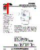
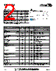
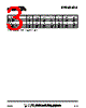
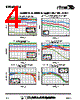
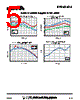
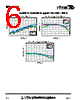
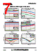
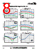
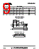
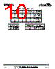


Okay, I've reviewed the provided text, which appears to be a datasheet or report containing graphs and data related to the performance of an RF (Radio Frequency) device, likely a power amplifier or similar component. Here's a breakdown of the key information and a summary:
Overall Content:
The document presents performance characteristics of an RF device across two frequency ranges:
️· 1.4 GHz - 2.7 GHz (First section)
️· 2.4 GHz - 2.7 GHz (Second section)
The data presented includes graphs and likely numerical values (not fully visible in the extracted text) for:
️· S-parameters: (Implied by descriptions of return loss, isolation)
️· Gain
️· Output Power (P1dB) - The output power at which the amplifier's gain starts to compress.
️· Third Order Intercept Point (IP3) - A measure of linearity, indicating the point where the third-order distortion products become equal to the fundamental signal.
️· Noise Figure (NF) - A measure of the noise added by the device.
️· Bit Error Rate (BER)
️· Attenuation
️· Return Loss (Input and Output)
️· Isolation
️· Performance vs. Temperature: Data is presented at +25°C, +85°C, and -40°C to show how the device's characteristics change with temperature.
️· Performance vs. Attenuation State: Graphs show how various performance parameters vary with different attenuation settings.
Key Observations and Summarized Data:
️· Frequency Range: The device is designed to operate effectively in the 1.4-2.7 GHz range, with more detailed data specifically focused on the 2.4-2.7 GHz band.
️· Performance Metrics: The graphs demonstrate the device's ability to amplify signals with relatively low noise.
️· Temperature Stability: Performance parameters are reported across a wide temperature range, allowing for a better understanding of the component's suitability in various operating conditions.
️· Linearity: Data regarding IP3 suggests the device has reasonable linearity, essential for applications requiring accurate signal reproduction.
️· Return Loss/Isolation: The device exhibits acceptable return loss and isolation characteristics, contributing to good signal integrity.
️· Attenuation Variation: The influence of varying the attenuation state is depicted on key graphs, aiding in signal optimization for specific application requirements.
️· Bit Error Rate (BER): It seems that a lower BER is preferable.
In essence, this document is a datasheet detailing the RF performance of a device, allowing engineers to assess its suitability for specific applications, such as wireless communication systems, radar, or test equipment.
If you provide specific questions about particular graphs or data points, I can provide more detailed analysis.
Overall Content:
The document presents performance characteristics of an RF device across two frequency ranges:
️· 1.4 GHz - 2.7 GHz (First section)
️· 2.4 GHz - 2.7 GHz (Second section)
The data presented includes graphs and likely numerical values (not fully visible in the extracted text) for:
️· S-parameters: (Implied by descriptions of return loss, isolation)
️· Gain
️· Output Power (P1dB) - The output power at which the amplifier's gain starts to compress.
️· Third Order Intercept Point (IP3) - A measure of linearity, indicating the point where the third-order distortion products become equal to the fundamental signal.
️· Noise Figure (NF) - A measure of the noise added by the device.
️· Bit Error Rate (BER)
️· Attenuation
️· Return Loss (Input and Output)
️· Isolation
️· Performance vs. Temperature: Data is presented at +25°C, +85°C, and -40°C to show how the device's characteristics change with temperature.
️· Performance vs. Attenuation State: Graphs show how various performance parameters vary with different attenuation settings.
Key Observations and Summarized Data:
️· Frequency Range: The device is designed to operate effectively in the 1.4-2.7 GHz range, with more detailed data specifically focused on the 2.4-2.7 GHz band.
️· Performance Metrics: The graphs demonstrate the device's ability to amplify signals with relatively low noise.
️· Temperature Stability: Performance parameters are reported across a wide temperature range, allowing for a better understanding of the component's suitability in various operating conditions.
️· Linearity: Data regarding IP3 suggests the device has reasonable linearity, essential for applications requiring accurate signal reproduction.
️· Return Loss/Isolation: The device exhibits acceptable return loss and isolation characteristics, contributing to good signal integrity.
️· Attenuation Variation: The influence of varying the attenuation state is depicted on key graphs, aiding in signal optimization for specific application requirements.
️· Bit Error Rate (BER): It seems that a lower BER is preferable.
In essence, this document is a datasheet detailing the RF performance of a device, allowing engineers to assess its suitability for specific applications, such as wireless communication systems, radar, or test equipment.
| Part No. | RFDA2026SR |
| Manufacturer | RFMD |
| Size | 1Mb |
| Pages | 16 pages |
| Description | DIGITAL CONTROLLED VARIABLE GAIN AMPLIFIER 1400MHz to 2700MHz, 6-BIT 0.5dB LSB CONTROL |
| ALLDATASHEET é útil para você? [ DONATE ] |
Sobre Alldatasheet | Publicidade | Contato conosco | Privacy Policy | Link para a ficha técnica | roca de Link | Lista de Fabricantes All Rights Reserved©Alldatasheet.com |
| Russian : Alldatasheetru.com | Korean : Alldatasheet.co.kr | Spanish : Alldatasheet.es | French : Alldatasheet.fr | Italian : Alldatasheetit.com Portuguese : Alldatasheetpt.com | Polish : Alldatasheet.pl | Vietnamese : Alldatasheet.vn Indian : Alldatasheet.in | Mexican : Alldatasheet.com.mx | British : Alldatasheet.co.uk | New Zealand : Alldatasheet.co.nz |
|
Family Site : ic2ic.com |
icmetro.com |
 Portuguese ▼
  English
 Chinese
 German
 Japanese
 Russian
 Korean
 Spanish
 French
 Italian
 Polish
 Vietnamese
 Indian
 Mexican
 British
 New Zealand