 |
Os motores de busca de Datasheet de Componentes eletrônicos |
|
|
Os motores de busca de Datasheet de Componentes eletrônicos |
|
The question interval is too short.
Please try again in a few seconds.

Hello, Please ask a question about RFDA0066 Datasheet
# Example questions:
➢ What is the relationship between the dsa1 control bits and the resulting gain relative to maximum gain?
➢ ) for the spi communication. what does 't4' specifically represent, and why is it important?
➢ What attenuation setting is achieved when the pup signal is set to 'low'?
| Part No. | RFDA0066 |
| Manufacturer | RFMD |
| Size | 1Mb |
| Pages | 18 pages |
| Description | DIGITAL CONTROLLED VARIABLE GAIN AMPLIFIER 5MHz TO 1GHz, 12-BIT 0.5dB LSB CONTROL |


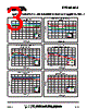


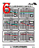


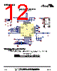


Okay, this is a long document! It appears to be a datasheet or application note for an RF component, likely an integrated circuit (IC) controlling gain and attenuation. Here's a breakdown of the key takeaways and a summary of the content:
Overall Purpose:
The document details the control and configuration of an RF component (likely a chip) that provides adjustable gain and attenuation. It covers:
️· Gain/Attenuation Control: The device uses digital control bits (D0-D11) to set the attenuation/gain in specific steps (0dB, -0.5dB, -1dB, -2dB, -4dB, -8dB, -16dB, -31.5dB).
️· SPI Interface: It communicates with a host controller using an SPI (Serial Peripheral Interface) protocol.
️· Power-up Programming: Defines how the device is initially configured at power-up.
Key Sections and What They Cover:
1. Gain/Attenuation Tables (Truth Tables): These tables map the digital control bit settings (D0-D11 for attenuation/gain control) to the actual attenuation/gain level achieved. There are two sets of control bits - one for DSA1 and one for DSA2.
2. SPI Timing Diagram: This is *critical* for interfacing with the device. It specifies the timing requirements for the SPI signals (Clock – CLK, Data In – DATA, Chip Enable/Load – LE, Data Out – DOUT) to ensure reliable communication. The timing parameters (t1, t2, t3, t4, etc.) define the minimum and maximum durations for signal transitions.
3. SPI Parameter Limits: A table defining the allowable limits for the SPI timing parameters.
4. Power-Up Programming: Describes how to configure the device upon power-up using the PUP pin.
Important Highlights:
️· SPI Communication: The device is controlled via SPI, so you’ll need a microcontroller or other SPI master to send commands.
️· Timing Critical: The SPI timing is very important. You *must* adhere to the specified timings to ensure that communication is successful.
️· Resolution: The gain/attenuation control offers discrete steps, not continuous adjustment.
️· Control Bits: Understanding the control bits (D0-D11) and how they map to gain/attenuation is essential for controlling the device.
️· Power-up Sequence: Ensure the correct PUP pin configuration during power-up.
In essence, this document provides the information needed to:
1. Connect: Physically interface the device with a host controller using the SPI bus.
2. Configure: Program the device's gain/attenuation settings via the SPI interface.
3. Operate: Use the device in an RF system with the desired gain/attenuation characteristics.
If you have specific questions about certain aspects, feel free to ask, and I'll do my best to answer based on the information provided in the document. For example, you might ask about the meaning of a specific timing parameter or the configuration of a control bit.
Overall Purpose:
The document details the control and configuration of an RF component (likely a chip) that provides adjustable gain and attenuation. It covers:
️· Gain/Attenuation Control: The device uses digital control bits (D0-D11) to set the attenuation/gain in specific steps (0dB, -0.5dB, -1dB, -2dB, -4dB, -8dB, -16dB, -31.5dB).
️· SPI Interface: It communicates with a host controller using an SPI (Serial Peripheral Interface) protocol.
️· Power-up Programming: Defines how the device is initially configured at power-up.
Key Sections and What They Cover:
1. Gain/Attenuation Tables (Truth Tables): These tables map the digital control bit settings (D0-D11 for attenuation/gain control) to the actual attenuation/gain level achieved. There are two sets of control bits - one for DSA1 and one for DSA2.
2. SPI Timing Diagram: This is *critical* for interfacing with the device. It specifies the timing requirements for the SPI signals (Clock – CLK, Data In – DATA, Chip Enable/Load – LE, Data Out – DOUT) to ensure reliable communication. The timing parameters (t1, t2, t3, t4, etc.) define the minimum and maximum durations for signal transitions.
3. SPI Parameter Limits: A table defining the allowable limits for the SPI timing parameters.
4. Power-Up Programming: Describes how to configure the device upon power-up using the PUP pin.
Important Highlights:
️· SPI Communication: The device is controlled via SPI, so you’ll need a microcontroller or other SPI master to send commands.
️· Timing Critical: The SPI timing is very important. You *must* adhere to the specified timings to ensure that communication is successful.
️· Resolution: The gain/attenuation control offers discrete steps, not continuous adjustment.
️· Control Bits: Understanding the control bits (D0-D11) and how they map to gain/attenuation is essential for controlling the device.
️· Power-up Sequence: Ensure the correct PUP pin configuration during power-up.
In essence, this document provides the information needed to:
1. Connect: Physically interface the device with a host controller using the SPI bus.
2. Configure: Program the device's gain/attenuation settings via the SPI interface.
3. Operate: Use the device in an RF system with the desired gain/attenuation characteristics.
| Part No. | RFDA0066 |
| Manufacturer | RFMD |
| Size | 1Mb |
| Pages | 18 pages |
| Description | DIGITAL CONTROLLED VARIABLE GAIN AMPLIFIER 5MHz TO 1GHz, 12-BIT 0.5dB LSB CONTROL |
| ALLDATASHEET é útil para você? [ DONATE ] |
Sobre Alldatasheet | Publicidade | Contato conosco | Privacy Policy | Link para a ficha técnica | roca de Link | Lista de Fabricantes All Rights Reserved©Alldatasheet.com |
| Russian : Alldatasheetru.com | Korean : Alldatasheet.co.kr | Spanish : Alldatasheet.es | French : Alldatasheet.fr | Italian : Alldatasheetit.com Portuguese : Alldatasheetpt.com | Polish : Alldatasheet.pl | Vietnamese : Alldatasheet.vn Indian : Alldatasheet.in | Mexican : Alldatasheet.com.mx | British : Alldatasheet.co.uk | New Zealand : Alldatasheet.co.nz |
|
Family Site : ic2ic.com |
icmetro.com |
 Portuguese ▼
  English
 Chinese
 German
 Japanese
 Russian
 Korean
 Spanish
 French
 Italian
 Polish
 Vietnamese
 Indian
 Mexican
 British
 New Zealand