 |
Os motores de busca de Datasheet de Componentes eletrônicos |
|
|
Os motores de busca de Datasheet de Componentes eletrônicos |
|
The question interval is too short.
Please try again in a few seconds.

Hello, Please ask a question about IRF7468 Datasheet
# Example questions:
➢ What feature is used to identify the part number and other markings on the package?
➢ The so-8 package datasheet specifies a maximum mold protrusion. what is the maximum allowable protrusion in millimeters?
➢ What is the recommended duty factor to use when calculating the maximum effective transient thermal impedance?
| Part No. | IRF7468 |
| Manufacturer | IRF |
| Size | 232 Kbytes |
| Pages | 8 pages |
| Description | Power MOSFET(Vdss=40V, Id=9.4A) |


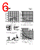


1. Device Overview & Specifications:
️· Device: International Rectifier (now Infineon) IRF7468 Power MOSFET
️· Type: N-Channel MOSFET
️· Voltage Rating (Vds): 60 V
️· Current Rating (Id): 100 A (Continuous)
️· Power Dissipation (Pd): 75 W
️· On-Resistance (Rds(on)): 0.48 Ohms @ Vgs = 10V, Id = 60A. (Note: Several values are provided at different Vgs and Id combinations)
️· Gate Threshold Voltage (Vgs(th)): 1V to 4V (Typical around 2V)
️· Package: SO-8 (Surface Mount)
️· Operating Temperature: -40°C to +125°C
2. Thermal Characteristics:
️· Thermal Resistance (Junction-to-Case, Rjc): 5.4°C/W
️· Thermal Resistance (Junction-to-Ambient, Rja): Depends heavily on the mounting conditions. Given a heat sink, it can be significantly lower than without.
️· Effective Transient Thermal Impedance: A graph (Figure 10) demonstrates the transient thermal impedance decreasing over time, which is important for pulsed power applications.
️· Avalanche Energy: Figure 14c provides maximum avalanche energy vs. drain current data.
3. Circuit Details & Test Conditions:
️· Gate Charge Test Circuit (Figure 13a&b): Shows a basic gate charge measurement setup, including a current regulator, resistors, and a waveform diagram.
️· Unclamped Inductive Test (Figure 14a&b): Illustrates the circuit for an Unclamped Inductive Test (UITT) and associated waveforms. This test is crucial for evaluating the device's robustness against inductive loads.
️· Current Sampling Resistors: Used in test setups to measure drain current.
4. Package Information (SO-8):
️· Dimensions: Detailed dimensions for the SO-8 package are provided (Figure 15). This includes:
- Overall dimensions
- Lead dimensions
- Footprint dimensions
- Pad layout
️· Part Marking: Details about the part marking on the SO-8 package.
️· Notes: Standards and tolerances are referenced (ANSI Y14.5M-1982).
5. Key Graphs and Tables (Highlights):
️· Dynamic Parameters: Shows switching characteristics.
️· Safe Operating Area: Graphical representation of maximum power dissipation versus temperature.
️· On-Resistance vs. Drain Current/Gate Voltage: Demonstrates the relationship between resistance and operating conditions.
1. Device Overview & Specifications:
️· Device: International Rectifier (now Infineon) IRF7468 Power MOSFET
️· Type: N-Channel MOSFET
️· Voltage Rating (Vds): 60 V
️· Current Rating (Id): 100 A (Continuous)
️· Power Dissipation (Pd): 75 W
️· On-Resistance (Rds(on)): 0.48 Ohms @ Vgs = 10V, Id = 60A. (Note: Several values are provided at different Vgs and Id combinations)
️· Gate Threshold Voltage (Vgs(th)): 1V to 4V (Typical around 2V)
️· Package: SO-8 (Surface Mount)
️· Operating Temperature: -40°C to +125°C
2. Thermal Characteristics:
️· Thermal Resistance (Junction-to-Case, Rjc): 5.4°C/W
️· Thermal Resistance (Junction-to-Ambient, Rja): Depends heavily on the mounting conditions. Given a heat sink, it can be significantly lower than without.
️· Effective Transient Thermal Impedance: A graph (Figure 10) demonstrates the transient thermal impedance decreasing over time, which is important for pulsed power applications.
️· Avalanche Energy: Figure 14c provides maximum avalanche energy vs. drain current data.
3. Circuit Details & Test Conditions:
️· Gate Charge Test Circuit (Figure 13a&b): Shows a basic gate charge measurement setup, including a current regulator, resistors, and a waveform diagram.
️· Unclamped Inductive Test (Figure 14a&b): Illustrates the circuit for an Unclamped Inductive Test (UITT) and associated waveforms. This test is crucial for evaluating the device's robustness against inductive loads.
️· Current Sampling Resistors: Used in test setups to measure drain current.
4. Package Information (SO-8):
️· Dimensions: Detailed dimensions for the SO-8 package are provided (Figure 15). This includes:
- Overall dimensions
- Lead dimensions
- Footprint dimensions
- Pad layout
️· Part Marking: Details about the part marking on the SO-8 package.
️· Notes: Standards and tolerances are referenced (ANSI Y14.5M-1982).
5. Key Graphs and Tables (Highlights):
️· Dynamic Parameters: Shows switching characteristics.
️· Safe Operating Area: Graphical representation of maximum power dissipation versus temperature.
️· On-Resistance vs. Drain Current/Gate Voltage: Demonstrates the relationship between resistance and operating conditions.
| Part No. | IRF7468 |
| Manufacturer | IRF |
| Size | 232 Kbytes |
| Pages | 8 pages |
| Description | Power MOSFET(Vdss=40V, Id=9.4A) |
| ALLDATASHEET é útil para você? [ DONATE ] |
Sobre Alldatasheet | Publicidade | Contato conosco | Privacy Policy | Link para a ficha técnica | roca de Link | Lista de Fabricantes All Rights Reserved©Alldatasheet.com |
| Russian : Alldatasheetru.com | Korean : Alldatasheet.co.kr | Spanish : Alldatasheet.es | French : Alldatasheet.fr | Italian : Alldatasheetit.com Portuguese : Alldatasheetpt.com | Polish : Alldatasheet.pl | Vietnamese : Alldatasheet.vn Indian : Alldatasheet.in | Mexican : Alldatasheet.com.mx | British : Alldatasheet.co.uk | New Zealand : Alldatasheet.co.nz |
|
Family Site : ic2ic.com |
icmetro.com |
 Portuguese ▼
  English
 Chinese
 German
 Japanese
 Russian
 Korean
 Spanish
 French
 Italian
 Polish
 Vietnamese
 Indian
 Mexican
 British
 New Zealand