 |
Os motores de busca de Datasheet de Componentes eletrônicos |
|
|
Os motores de busca de Datasheet de Componentes eletrônicos |
|
The question interval is too short.
Please try again in a few seconds.

Hello, Please ask a question about 2SC4227 Datasheet
# Example questions:
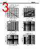
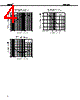
➢ Compare and contrast the s11 parameter (magnitude) behavior at 100 mhz across the three different collector current (ic) conditions (3ma, 7ma, and an unspecified value). what trends can you observe?
➢ Considering only the data at 7ma ic, what is the approximate -3db bandwidth of the device (the frequency range where the magnitude of s21 drops to half its maximum value)?
➢ For the 7ma ic condition, what is the approximate change in s21 (magnitude) from 100 mhz to 2000 mhz? express this change in db.
| Part No. | 2SC4227 |
| Manufacturer | NEC |
| Size | 50 Kbytes |
| Pages | 8 pages |
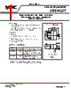
| Description | HIGH FREQUENCY LOW NOISE AMPLIFIER NPN SILICON EPITAXIAL TRANSISTOR SUPER MINI MOLD |



1. Document Overview & Legal Notices:
️· Product: NEC 2SC4227 transistor
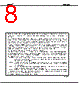
️· Copyright: NEC Corporation owns the copyright. Reproduction is prohibited without permission.
️· Disclaimer: NEC Corporation assumes no responsibility for errors in the document and disclaims liability for intellectual property infringement.
️· Quality Grades: NEC devices are classified into "Standard," "Special," and "Specific" quality grades, dictating appropriate applications. "Standard" is the default unless otherwise noted.
️· Application Restrictions: There's a list of device applications suitable for each quality grade and a warning about applications that should be discussed with NEC sales before use, particularly for higher-risk applications. (Aircraft, life support equipment, etc.)
️· Safety Note: A warning about incorporating safety measures due to the possibility of defects.
️· Anti-radioactive design: Device lacks anti-radioactive design.
2. Performance Data (S-Parameters):
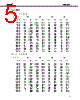
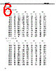
The core of the document consists of S-Parameter data at various frequencies (100 MHz to 3000 MHz) for three different bias conditions:
️· Vce = 3V, Ic = 7mA, Zo = 50Ω (This appears to be the main operating condition)
️· Vce = 3V, Ic = 7mA, Zo = 50Ω (Reiterated)
️· Vce = 3V, Ic = 7mA, Zo = 50Ω (Reiterated)
️· Vce = 3V, Ic = 7mA, Zo = 50Ω (Reiterated)
For each bias condition, the data presents:
️· S11 (Reflection Coefficient): Represents how much signal is reflected back from the transistor. Indicates the input match.
️· S21 (Forward Transmission Coefficient): Represents the signal gain through the transistor. How much signal passes through.
️· S12 (Reverse Transmission Coefficient): Signal reflected from output to input.
️· S22 (Isolation Coefficient): Represents how much signal is isolated from the output. Indicates the output match.
In simpler terms:
️· S11 (Return Loss): A low value is good – it means most of the signal is going *into* the transistor, not bouncing back.
️· S21 (Gain): A high value is generally desirable - it means the transistor is amplifying the signal.
️· S12: A low value is desirable, as it indicates minimal signal leakage from output to input
️· S22: A low value is desirable, as it indicates minimal signal leakage from input to output
What does this tell us?
This data allows engineers to model the transistor's behavior in a circuit, design matching networks to optimize signal transfer, and generally understand how well the transistor will perform.
Additional Notes:
️· Zo = 50Ω: This indicates the transistor is designed for a 50-ohm impedance system, a common standard in RF and microwave circuits.
️· "M4 94.11": This likely is a document reference or revision number.
️· "MEMO": Indicates a section possibly intended for notes or comments.
1. Document Overview & Legal Notices:
️· Product: NEC 2SC4227 transistor
️· Copyright: NEC Corporation owns the copyright. Reproduction is prohibited without permission.
️· Disclaimer: NEC Corporation assumes no responsibility for errors in the document and disclaims liability for intellectual property infringement.
️· Quality Grades: NEC devices are classified into "Standard," "Special," and "Specific" quality grades, dictating appropriate applications. "Standard" is the default unless otherwise noted.
️· Application Restrictions: There's a list of device applications suitable for each quality grade and a warning about applications that should be discussed with NEC sales before use, particularly for higher-risk applications. (Aircraft, life support equipment, etc.)
️· Safety Note: A warning about incorporating safety measures due to the possibility of defects.
️· Anti-radioactive design: Device lacks anti-radioactive design.
2. Performance Data (S-Parameters):
The core of the document consists of S-Parameter data at various frequencies (100 MHz to 3000 MHz) for three different bias conditions:
️· Vce = 3V, Ic = 7mA, Zo = 50Ω (This appears to be the main operating condition)
️· Vce = 3V, Ic = 7mA, Zo = 50Ω (Reiterated)
️· Vce = 3V, Ic = 7mA, Zo = 50Ω (Reiterated)
️· Vce = 3V, Ic = 7mA, Zo = 50Ω (Reiterated)
For each bias condition, the data presents:
️· S11 (Reflection Coefficient): Represents how much signal is reflected back from the transistor. Indicates the input match.
️· S21 (Forward Transmission Coefficient): Represents the signal gain through the transistor. How much signal passes through.
️· S12 (Reverse Transmission Coefficient): Signal reflected from output to input.
️· S22 (Isolation Coefficient): Represents how much signal is isolated from the output. Indicates the output match.
In simpler terms:
️· S11 (Return Loss): A low value is good – it means most of the signal is going *into* the transistor, not bouncing back.
️· S21 (Gain): A high value is generally desirable - it means the transistor is amplifying the signal.
️· S12: A low value is desirable, as it indicates minimal signal leakage from output to input
️· S22: A low value is desirable, as it indicates minimal signal leakage from input to output
What does this tell us?
This data allows engineers to model the transistor's behavior in a circuit, design matching networks to optimize signal transfer, and generally understand how well the transistor will perform.
Additional Notes:
️· Zo = 50Ω: This indicates the transistor is designed for a 50-ohm impedance system, a common standard in RF and microwave circuits.
️· "M4 94.11": This likely is a document reference or revision number.
️· "MEMO": Indicates a section possibly intended for notes or comments.
| Part No. | 2SC4227 |
| Manufacturer | NEC |
| Size | 50 Kbytes |
| Pages | 8 pages |
| Description | HIGH FREQUENCY LOW NOISE AMPLIFIER NPN SILICON EPITAXIAL TRANSISTOR SUPER MINI MOLD |
| ALLDATASHEET é útil para você? [ DONATE ] |
Sobre Alldatasheet | Publicidade | Contato conosco | Privacy Policy | Link para a ficha técnica | roca de Link | Lista de Fabricantes All Rights Reserved©Alldatasheet.com |
| Russian : Alldatasheetru.com | Korean : Alldatasheet.co.kr | Spanish : Alldatasheet.es | French : Alldatasheet.fr | Italian : Alldatasheetit.com Portuguese : Alldatasheetpt.com | Polish : Alldatasheet.pl | Vietnamese : Alldatasheet.vn Indian : Alldatasheet.in | Mexican : Alldatasheet.com.mx | British : Alldatasheet.co.uk | New Zealand : Alldatasheet.co.nz |
|
Family Site : ic2ic.com |
icmetro.com |
 Portuguese ▼
  English
 Chinese
 German
 Japanese
 Russian
 Korean
 Spanish
 French
 Italian
 Polish
 Vietnamese
 Indian
 Mexican
 British
 New Zealand