 |
Os motores de busca de Datasheet de Componentes eletrônicos |
|
|
Os motores de busca de Datasheet de Componentes eletrônicos |
|
The question interval is too short.
Please try again in a few seconds.

Hello, Please ask a question about MCP6241 Datasheet
# Example questions:
➢ What is the typical thermal resistance (θja) for the mcp6241 in an 8-lead msop package?
➢ What is the maximum junction temperature (tj) specification for the mcp6241?
➢ How does the input bias current change with temperature?
| Part No. | MCP6241 |
| Manufacturer | MICROCHIP |
| Size | 689 Kbytes |
| Pages | 38 pages |
| Description | 50 關A, 550 kHz Rail-to-Rail Op Amp |







1. Device Overview
️· Product: MCP6241/1R/1U/2/4 (Operational Amplifiers)
️· Document: DS21882D
2. Key Specifications (Excerpts - Full datasheet needed for complete details)
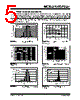
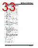
️· Typical Performance Curves: Many curves (PSRR, CMRR, Gain, Input Bias Current, etc.) are provided for various conditions (temperature, supply voltage, frequency).
️· Power Supply Voltage: The specifications are shown with VDD = 1.8V and 5.5V.
️· Ambient Temperature: Curves shown for -40°C, +25°C, +85°C, and +125°C.
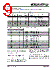
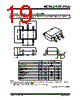
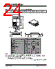
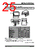
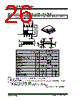
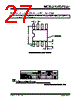
️· Thermal Resistances: Important for calculating junction temperature (Tj) and preventing overheating. Values provided for various package types (SC70, SOT-23, DFN, MSOP, PDIP, SOIC, TSSOP).
3. Important Figures & Curves (Summarized)
️· Figure 2-1: Input Offset Voltage: Shows how input offset voltage changes with temperature.
️· Figure 2-2: PSRR and CMRR vs. Frequency: Illustrates the Power Supply Rejection Ratio (PSRR) and Common-Mode Rejection Ratio (CMRR) characteristics over a range of frequencies. Performance typically degrades at higher frequencies.
️· Figure 2-3: Input Bias Current at +85°C: Illustrates the input bias current behavior at a specific temperature.
️· Figure 2-4: CMRR, PSRR vs. Ambient Temperature: Shows how the Common-Mode Rejection Ratio and Power Supply Rejection Ratio vary with temperature.
️· Figure 2-5: Open-Loop Gain and Phase vs. Frequency: Depicts the open-loop gain and phase shift behavior of the amplifier as a function of frequency.
️· Figure 2-6: Input Bias Current at +125°C: Illustrates the input bias current behavior at a higher temperature.
4. Thermal Information
️· Junction Temperature (Tj): Must not exceed +150°C.
️· θJA (Thermal Resistance): Values provided for different package types, allowing calculation of the junction temperature based on ambient temperature and power dissipation. (Important for thermal design).
5. Test Circuits
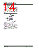
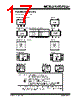
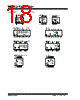
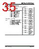
️· Figure 2-1: AC and DC test circuit for most non-inverting gain conditions.
️· Figure 2-2: AC and DC test circuit for most inverting gain conditions.
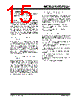
️· The test circuits used bypass capacitors according to the rules outlined in Section 4.6 of the full document.
Key Takeaways & Considerations:
️· Temperature Dependence: The performance of the amplifier (offset voltage, bias current, rejection ratios) is significantly affected by temperature. Careful consideration must be given to operating temperature ranges.
️· Frequency Response: The amplifier's gain and phase response degrade at higher frequencies.
️· Thermal Management: The thermal resistance values are essential for ensuring the amplifier's junction temperature remains below the maximum specified value. Proper heat sinking or PCB layout may be necessary.
️· Complete Datasheet: This extract provides a partial view. A complete datasheet is needed for comprehensive specifications, absolute maximum ratings, application circuits, and other critical information.
1. Device Overview
️· Product: MCP6241/1R/1U/2/4 (Operational Amplifiers)
️· Document: DS21882D
2. Key Specifications (Excerpts - Full datasheet needed for complete details)
️· Typical Performance Curves: Many curves (PSRR, CMRR, Gain, Input Bias Current, etc.) are provided for various conditions (temperature, supply voltage, frequency).
️· Power Supply Voltage: The specifications are shown with VDD = 1.8V and 5.5V.
️· Ambient Temperature: Curves shown for -40°C, +25°C, +85°C, and +125°C.
️· Thermal Resistances: Important for calculating junction temperature (Tj) and preventing overheating. Values provided for various package types (SC70, SOT-23, DFN, MSOP, PDIP, SOIC, TSSOP).
3. Important Figures & Curves (Summarized)
️· Figure 2-1: Input Offset Voltage: Shows how input offset voltage changes with temperature.
️· Figure 2-2: PSRR and CMRR vs. Frequency: Illustrates the Power Supply Rejection Ratio (PSRR) and Common-Mode Rejection Ratio (CMRR) characteristics over a range of frequencies. Performance typically degrades at higher frequencies.
️· Figure 2-3: Input Bias Current at +85°C: Illustrates the input bias current behavior at a specific temperature.
️· Figure 2-4: CMRR, PSRR vs. Ambient Temperature: Shows how the Common-Mode Rejection Ratio and Power Supply Rejection Ratio vary with temperature.
️· Figure 2-5: Open-Loop Gain and Phase vs. Frequency: Depicts the open-loop gain and phase shift behavior of the amplifier as a function of frequency.
️· Figure 2-6: Input Bias Current at +125°C: Illustrates the input bias current behavior at a higher temperature.
4. Thermal Information
️· Junction Temperature (Tj): Must not exceed +150°C.
️· θJA (Thermal Resistance): Values provided for different package types, allowing calculation of the junction temperature based on ambient temperature and power dissipation. (Important for thermal design).
5. Test Circuits
️· Figure 2-1: AC and DC test circuit for most non-inverting gain conditions.
️· Figure 2-2: AC and DC test circuit for most inverting gain conditions.
️· The test circuits used bypass capacitors according to the rules outlined in Section 4.6 of the full document.
Key Takeaways & Considerations:
️· Temperature Dependence: The performance of the amplifier (offset voltage, bias current, rejection ratios) is significantly affected by temperature. Careful consideration must be given to operating temperature ranges.
️· Frequency Response: The amplifier's gain and phase response degrade at higher frequencies.
️· Thermal Management: The thermal resistance values are essential for ensuring the amplifier's junction temperature remains below the maximum specified value. Proper heat sinking or PCB layout may be necessary.
️· Complete Datasheet: This extract provides a partial view. A complete datasheet is needed for comprehensive specifications, absolute maximum ratings, application circuits, and other critical information.
| Part No. | MCP6241 |
| Manufacturer | MICROCHIP |
| Size | 689 Kbytes |
| Pages | 38 pages |
| Description | 50 關A, 550 kHz Rail-to-Rail Op Amp |
| ALLDATASHEET é útil para você? [ DONATE ] |
Sobre Alldatasheet | Publicidade | Contato conosco | Privacy Policy | Link para a ficha técnica | roca de Link | Lista de Fabricantes All Rights Reserved©Alldatasheet.com |
| Russian : Alldatasheetru.com | Korean : Alldatasheet.co.kr | Spanish : Alldatasheet.es | French : Alldatasheet.fr | Italian : Alldatasheetit.com Portuguese : Alldatasheetpt.com | Polish : Alldatasheet.pl | Vietnamese : Alldatasheet.vn Indian : Alldatasheet.in | Mexican : Alldatasheet.com.mx | British : Alldatasheet.co.uk | New Zealand : Alldatasheet.co.nz |
|
Family Site : ic2ic.com |
icmetro.com |
 Portuguese ▼
  English
 Chinese
 German
 Japanese
 Russian
 Korean
 Spanish
 French
 Italian
 Polish
 Vietnamese
 Indian
 Mexican
 British
 New Zealand