 |
Os motores de busca de Datasheet de Componentes eletrônicos |
|
|
Os motores de busca de Datasheet de Componentes eletrônicos |
|
The question interval is too short.
Please try again in a few seconds.

Hello, Please ask a question about SM8146AD1 Datasheet
# Example questions:
➢ What happens to the output voltage when the input reaches 8 pulses?
➢ How does the output voltage change as the number of input pulses increases from 0 to 7? be specific about the trend.
➢ What is the range of output voltages presented in the data, from the lowest to the highest?
| Part No. | SM8146AD1 |
| Manufacturer | NPC |
| Size | 304 Kbytes |
| Pages | 19 pages |
| Description | EL Driver IC |




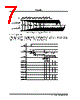

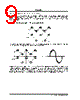


Okay, let's break down this documentation excerpt. It describes the behavior of an LED brightness control system (likely for an EL backlight, based on the voltages mentioned).
1. Overall Functionality:
️· The document details how to control the brightness of an LED backlight using a microcontroller. The brightness is adjusted by varying the duty cycle of a PWM (Pulse Width Modulation) signal.
️· The PWM signal drives a MOSFET (Metal-Oxide-Semiconductor Field-Effect Transistor), which acts as a switch controlling the current flowing to the LED backlight.
2. Key Components & Concepts:
️· LED Backlight: The device being controlled. EL Backlights are common for LCD screens.
️· Microcontroller: The brain of the system, generating the PWM signal.
️· PWM (Pulse Width Modulation): A technique for varying the average voltage applied to the LED backlight. The "duty cycle" is the percentage of time the signal is "high" (on). Higher duty cycle = brighter LED.
️· MOSFET: A transistor used as a switch. The microcontroller's PWM signal controls the MOSFET, which in turn controls the power delivered to the LED.
️· Duty Cycle: The ratio of the "on" time to the total PWM period. It ranges from 0% (off) to 100% (full brightness).
️· Voltage Levels:
- 0V: LED backlight completely off.
- 43V, 50V, 37V, 71V, 156V/128V/100V: These voltages represent intermediate brightness levels. The higher the voltage, the brighter the LED backlight. The 156/128/100V readings likely represent the voltage across the LED when it's operating at the maximum brightness level.
️· PWM Period: The table illustrates that the values for the brightness levels are dependent on the PWM period.
3. Brightness Level Table Breakdown:
The large table provides the PWM duty cycle and corresponding voltage values for various brightness levels. Let’s examine this a little better:
️· Columns:
- PWM Duty Cycle: Percentage (0% to 100%)
- Voltage Values: Values (at different values of PWM Period) – These represent the voltage applied to the LED backlight at each duty cycle.
️· Rows:
- The table lists various brightness levels and the corresponding PWM settings.
- The last few rows represent special cases such as 0% duty cycle (completely off) and maximum duty cycle (full brightness). The values in those rows represent the voltage levels across the LED Backlight.
4. Important Observations & Interpretations:
️· Non-Linearity: The relationship between duty cycle and brightness is not perfectly linear. Small changes in duty cycle at lower brightness levels produce noticeable changes in brightness, while larger changes are needed at higher brightness levels to achieve the same perceived change in brightness.
️· Specific Voltages: The table provides specific voltage targets for several brightness levels. These levels can be used by the microcontroller to adjust the PWM duty cycle to achieve the desired brightness.
️· PWM Period: Different PWM periods are illustrated for the various table values.
In summary: This documentation describes a controlled backlight system. The microcontroller uses PWM to control the MOSFET, which in turn controls the voltage/brightness of the backlight. The table gives an outline of the levels for a user or developer to configure the brightness.
1. Overall Functionality:
️· The document details how to control the brightness of an LED backlight using a microcontroller. The brightness is adjusted by varying the duty cycle of a PWM (Pulse Width Modulation) signal.
️· The PWM signal drives a MOSFET (Metal-Oxide-Semiconductor Field-Effect Transistor), which acts as a switch controlling the current flowing to the LED backlight.
2. Key Components & Concepts:
️· LED Backlight: The device being controlled. EL Backlights are common for LCD screens.
️· Microcontroller: The brain of the system, generating the PWM signal.
️· PWM (Pulse Width Modulation): A technique for varying the average voltage applied to the LED backlight. The "duty cycle" is the percentage of time the signal is "high" (on). Higher duty cycle = brighter LED.
️· MOSFET: A transistor used as a switch. The microcontroller's PWM signal controls the MOSFET, which in turn controls the power delivered to the LED.
️· Duty Cycle: The ratio of the "on" time to the total PWM period. It ranges from 0% (off) to 100% (full brightness).
️· Voltage Levels:
- 0V: LED backlight completely off.
- 43V, 50V, 37V, 71V, 156V/128V/100V: These voltages represent intermediate brightness levels. The higher the voltage, the brighter the LED backlight. The 156/128/100V readings likely represent the voltage across the LED when it's operating at the maximum brightness level.
️· PWM Period: The table illustrates that the values for the brightness levels are dependent on the PWM period.
3. Brightness Level Table Breakdown:
The large table provides the PWM duty cycle and corresponding voltage values for various brightness levels. Let’s examine this a little better:
️· Columns:
- PWM Duty Cycle: Percentage (0% to 100%)
- Voltage Values: Values (at different values of PWM Period) – These represent the voltage applied to the LED backlight at each duty cycle.
️· Rows:
- The table lists various brightness levels and the corresponding PWM settings.
- The last few rows represent special cases such as 0% duty cycle (completely off) and maximum duty cycle (full brightness). The values in those rows represent the voltage levels across the LED Backlight.
4. Important Observations & Interpretations:
️· Non-Linearity: The relationship between duty cycle and brightness is not perfectly linear. Small changes in duty cycle at lower brightness levels produce noticeable changes in brightness, while larger changes are needed at higher brightness levels to achieve the same perceived change in brightness.
️· Specific Voltages: The table provides specific voltage targets for several brightness levels. These levels can be used by the microcontroller to adjust the PWM duty cycle to achieve the desired brightness.
️· PWM Period: Different PWM periods are illustrated for the various table values.
In summary: This documentation describes a controlled backlight system. The microcontroller uses PWM to control the MOSFET, which in turn controls the voltage/brightness of the backlight. The table gives an outline of the levels for a user or developer to configure the brightness.
| Part No. | SM8146AD1 |
| Manufacturer | NPC |
| Size | 304 Kbytes |
| Pages | 19 pages |
| Description | EL Driver IC |
| ALLDATASHEET é útil para você? [ DONATE ] |
Sobre Alldatasheet | Publicidade | Contato conosco | Privacy Policy | Link para a ficha técnica | roca de Link | Lista de Fabricantes All Rights Reserved©Alldatasheet.com |
| Russian : Alldatasheetru.com | Korean : Alldatasheet.co.kr | Spanish : Alldatasheet.es | French : Alldatasheet.fr | Italian : Alldatasheetit.com Portuguese : Alldatasheetpt.com | Polish : Alldatasheet.pl | Vietnamese : Alldatasheet.vn Indian : Alldatasheet.in | Mexican : Alldatasheet.com.mx | British : Alldatasheet.co.uk | New Zealand : Alldatasheet.co.nz |
|
Family Site : ic2ic.com |
icmetro.com |
 Portuguese ▼
  English
 Chinese
 German
 Japanese
 Russian
 Korean
 Spanish
 French
 Italian
 Polish
 Vietnamese
 Indian
 Mexican
 British
 New Zealand