 |
Os motores de busca de Datasheet de Componentes eletrônicos |
|
|
Os motores de busca de Datasheet de Componentes eletrônicos |
|
The question interval is too short.
Please try again in a few seconds.

Hello, Please ask a question about UT63M-147CCC Datasheet
# Example questions:
➢ What is the maximum allowable overshoot or ring distortion (vdis) for a transformer-coupled stub configuration?
➢ What are the primary differences in isolation transformer ratios for direct-coupled and transformer-coupled configurations, as specified in table 2?
➢ What is the maximum allowable propagation delay (trcvpd) for the receiver?
| Part No. | UT63M-147CCC |
| Manufacturer | AEROFLEX |
| Size | 1Mb |
| Pages | 20 pages |
| Description | MIL-STD-1553A/B Bus Transceiver |






1. Introduction & Purpose
️· This document details the electrical characteristics of a transceiver designed to comply with MIL-STD-1553, a standard for data communication on military systems. It appears to be a detailed specification for engineers and technicians working with or designing equipment incorporating this transceiver.
2. Key Technologies & Coupling Methods
️· Direct Coupling: Uses an isolation transformer with a ratio of 2.5:1.
️· Transformer Coupling: Utilizes an isolation transformer with a ratio of 1.79:1, with another transformer for overall coupling with a ratio of 1:1.4.
3. Electrical Characteristics (Major Highlights)
️· Output Voltage Swing (Transmitter):
- Direct-coupled: 18-27 Vpp (peak-to-peak)
- Transformer-coupled: 6.0-20 Vpp
️· Output Noise (Transmitter): ≤ 14 mVpp (transformer-coupled) ≤ 5 mVpp (direct-coupled)
️· Output Symmetry (Transmitter): ± 250 mVpp (direct-coupled), ± 90 mVpp (transformer-coupled).
️· Output Distortion (Transmitter): ≤ ± 900 mVpeak (direct-coupled), ≤ ± 300 mVpeak (transformer-coupled).
️· Receiver Propagation Delay: ≤ 450ns
️· Transmitter Propagation Delay: ≤ 200ns
️· Rise and Fall Time (Transmitter Output): 100 - 300ns
️· Zero Crossing Distortion: -150 to +150ns
️· Zero Crossing Stability: -25 to +25ns
️· Transmitter Inhibited Time: On: ≤ 150ns, Off: ≤100ns
4. AC Characteristics (Timing)
The document provides timing specifications for various functions, including:
️· Receiver Output Delay: ≤ 200ns
️· Transmitter Input Skew: ≤ 25ns
️· Receiver Propagation Delay: ≤ 450ns
️· Transmitter Propagation Delay: ≤ 200ns
️· Many other timing details related to signal transitions and inhibition.
5. Transformer Requirements
️· Direct Coupling Isolation Transformer Ratio: 2.5:1
️· Transformer Coupling Isolation Transformer Ratio: 1.79:1
️· Coupling Transformer Ratio: 1:1.4
6. Testing and Qualification
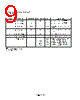
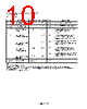
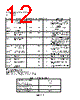
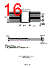
️· The document references testing figures (Figure 9, 10, 11, 12, 13) for performance evaluation and qualification.
️· It mentions compliance with MIL-HDBK-1553 for Common Mode Rejection.
NOTES – *READ THIS CAREFULLY*
️· Context is King: This is *part* of a much larger document (indicated by "Appendix 2 - X"). Without the preceding sections, some terms and references might be unclear.
️· MIL-STD-1553: You *must* understand the fundamentals of MIL-STD-1553 to fully interpret this data. This is a complex, bus-based communication protocol used extensively in military and aerospace systems.
️· "Vpp," "Vpeak," "ns": These are electrical engineering abbreviations. Understand their meaning (Vpp = volts peak-to-peak, Vpeak = volts peak, ns = nanoseconds).
️· Direct vs. Transformer Coupling: The key differences between these methods significantly impact performance characteristics. Pay close attention to the specifications for each.
️· Figure References: The document relies heavily on figures (9, 10, 11, 12, 13) to illustrate waveforms and test setups. Obtaining and examining these figures is *essential* for anyone working with this data.
️· "Guaranteed by Design": Some characteristics are indicated as "Guaranteed by design" – meaning they aren’t actively tested, but are expected to be met based on design calculations.
️· Table 2: Provides critical transformer ratio requirements for different coupling methods.
️· "Supplied as a Design Limit": This denotes characteristics which are considered as a design constraint, but not subject to strict testing.
1. Introduction & Purpose
️· This document details the electrical characteristics of a transceiver designed to comply with MIL-STD-1553, a standard for data communication on military systems. It appears to be a detailed specification for engineers and technicians working with or designing equipment incorporating this transceiver.
2. Key Technologies & Coupling Methods
️· Direct Coupling: Uses an isolation transformer with a ratio of 2.5:1.
️· Transformer Coupling: Utilizes an isolation transformer with a ratio of 1.79:1, with another transformer for overall coupling with a ratio of 1:1.4.
3. Electrical Characteristics (Major Highlights)
️· Output Voltage Swing (Transmitter):
- Direct-coupled: 18-27 Vpp (peak-to-peak)
- Transformer-coupled: 6.0-20 Vpp
️· Output Noise (Transmitter): ≤ 14 mVpp (transformer-coupled) ≤ 5 mVpp (direct-coupled)
️· Output Symmetry (Transmitter): ± 250 mVpp (direct-coupled), ± 90 mVpp (transformer-coupled).
️· Output Distortion (Transmitter): ≤ ± 900 mVpeak (direct-coupled), ≤ ± 300 mVpeak (transformer-coupled).
️· Receiver Propagation Delay: ≤ 450ns
️· Transmitter Propagation Delay: ≤ 200ns
️· Rise and Fall Time (Transmitter Output): 100 - 300ns
️· Zero Crossing Distortion: -150 to +150ns
️· Zero Crossing Stability: -25 to +25ns
️· Transmitter Inhibited Time: On: ≤ 150ns, Off: ≤100ns
4. AC Characteristics (Timing)
The document provides timing specifications for various functions, including:
️· Receiver Output Delay: ≤ 200ns
️· Transmitter Input Skew: ≤ 25ns
️· Receiver Propagation Delay: ≤ 450ns
️· Transmitter Propagation Delay: ≤ 200ns
️· Many other timing details related to signal transitions and inhibition.
5. Transformer Requirements
️· Direct Coupling Isolation Transformer Ratio: 2.5:1
️· Transformer Coupling Isolation Transformer Ratio: 1.79:1
️· Coupling Transformer Ratio: 1:1.4
6. Testing and Qualification
️· The document references testing figures (Figure 9, 10, 11, 12, 13) for performance evaluation and qualification.
️· It mentions compliance with MIL-HDBK-1553 for Common Mode Rejection.
NOTES – *READ THIS CAREFULLY*
️· Context is King: This is *part* of a much larger document (indicated by "Appendix 2 - X"). Without the preceding sections, some terms and references might be unclear.
️· MIL-STD-1553: You *must* understand the fundamentals of MIL-STD-1553 to fully interpret this data. This is a complex, bus-based communication protocol used extensively in military and aerospace systems.
️· "Vpp," "Vpeak," "ns": These are electrical engineering abbreviations. Understand their meaning (Vpp = volts peak-to-peak, Vpeak = volts peak, ns = nanoseconds).
️· Direct vs. Transformer Coupling: The key differences between these methods significantly impact performance characteristics. Pay close attention to the specifications for each.
️· Figure References: The document relies heavily on figures (9, 10, 11, 12, 13) to illustrate waveforms and test setups. Obtaining and examining these figures is *essential* for anyone working with this data.
️· "Guaranteed by Design": Some characteristics are indicated as "Guaranteed by design" – meaning they aren’t actively tested, but are expected to be met based on design calculations.
️· Table 2: Provides critical transformer ratio requirements for different coupling methods.
️· "Supplied as a Design Limit": This denotes characteristics which are considered as a design constraint, but not subject to strict testing.
| Part No. | UT63M-147CCC |
| Manufacturer | AEROFLEX |
| Size | 1Mb |
| Pages | 20 pages |
| Description | MIL-STD-1553A/B Bus Transceiver |
| ALLDATASHEET é útil para você? [ DONATE ] |
Sobre Alldatasheet | Publicidade | Contato conosco | Privacy Policy | Link para a ficha técnica | roca de Link | Lista de Fabricantes All Rights Reserved©Alldatasheet.com |
| Russian : Alldatasheetru.com | Korean : Alldatasheet.co.kr | Spanish : Alldatasheet.es | French : Alldatasheet.fr | Italian : Alldatasheetit.com Portuguese : Alldatasheetpt.com | Polish : Alldatasheet.pl | Vietnamese : Alldatasheet.vn Indian : Alldatasheet.in | Mexican : Alldatasheet.com.mx | British : Alldatasheet.co.uk | New Zealand : Alldatasheet.co.nz |
|
Family Site : ic2ic.com |
icmetro.com |
 Portuguese ▼
  English
 Chinese
 German
 Japanese
 Russian
 Korean
 Spanish
 French
 Italian
 Polish
 Vietnamese
 Indian
 Mexican
 British
 New Zealand